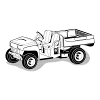
Figure43
1.Left-handA-arm
6.Torquetherideheightadjustmentboltto
135-165ft-lb(183-224N-m).
7.Replacethetravellimitingbolt(Figure42).
Note:Thevehiclemayneedtobeloweredtothe
groundonthatsidetoinstallthebolt.
8.Tightenandtorquethecenteringboltsto
240-290ft-lb(325-393N-m).
9.Checktherideheightatthefronttongueperthe
dimensionsandparametersgivenatthebeginningof
thisprocedure.
AdjustingFrontWheelToe-In
Checkthefrontwheeltoe-inafterevery100operating
hours,orannually,whicheveroccursrst.
Thetoe-inshouldbe1/8-5/8inch(3-16mm)withthe
followingparameters:
•Thetirepressureshouldbeat12psi(83kPa).
•Therideheightshouldbecorrectbeforesettingthe
toe-in;refertoAdjustingtheFrontSuspension.
•Thevehicleshouldbedrivenbackandforthafew
timestorelaxtheA-arms.
•Measurethetoe-inwiththewheelsfacingstraight
aheadanda175-225lb(79-102kg)operatorinthe
driver’sseat.
Note:Thedrivershoulddriveuptothe
measurementareaandstayseatedinthevehicle
whilethemeasurementisbeingtaken.
Ifthevehiclewillberunwithmediumtoheavyloads
mostofthetime,setthetoe-inonthehighsideof
therecommendedamount.Ifitisgoingtoberun
withalightloadmostofthetime,setthetoe-inon
thelowsideoftherecommendedamount.
1.Ensurethatthefrontsuspensionisadjusted
properly;refertoAdjustingtheFrontSuspension.
Adjustifnecessary.
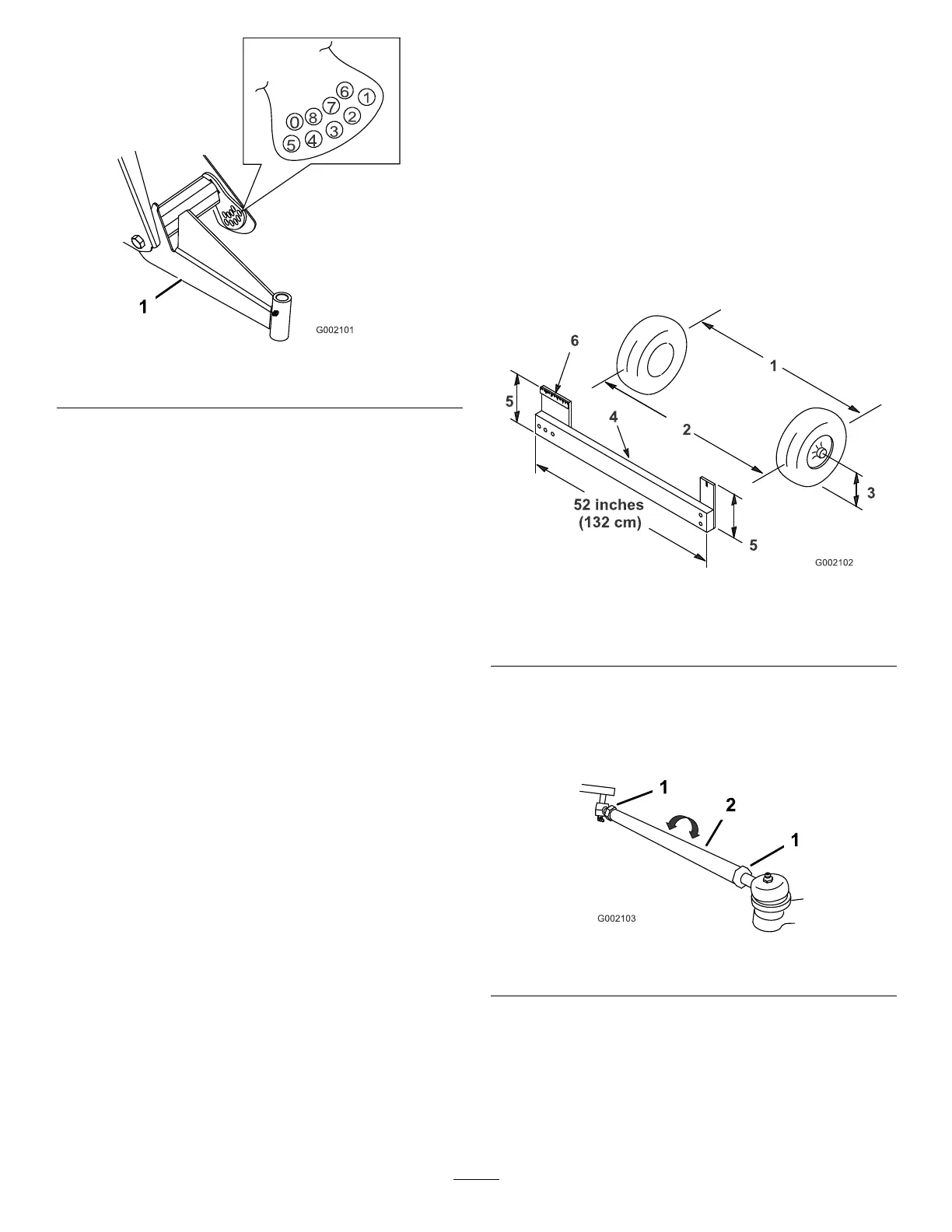
2.Measurethedistancebetweenbothofthefronttires
attheaxleheightatboththefrontandrearofthe
fronttires(Figure44).Axtureoralignmentgauge
isneededfortherearmeasurementofthefronttires
ataxleheight.Usethesamextureoralignment
gaugetoaccuratelymeasurethefrontofthefront
tiresataxleheight(Figure44).
Figure44
1.Tirecenterline-back4.Fixture
2.Tirecenterline-front
5.Axlecenterlinedistance
3.Axlecenterline
6.6inches(15cm)ruler
3.Ifthemeasurementdoesnotfallwithinthespecied
range(refertothedimensionsandparametersatthe
beginningofthisprocedure),loosenthejamnutsat
bothendsofthetierods(Figure45).
Figure45
1.Jamnut2.Tierod
4.Rotatebothtierodstomovethefrontofthetire
inwardoroutward.
5.Tightenthetierodjamnutswhentheadjustmentis
correct.
6.Ensurethatthereisfulltravelofthesteeringwheel
inbothdirections.
35
 Loading...