1800 POWER CURVE
3Service Instruction TSN0001a
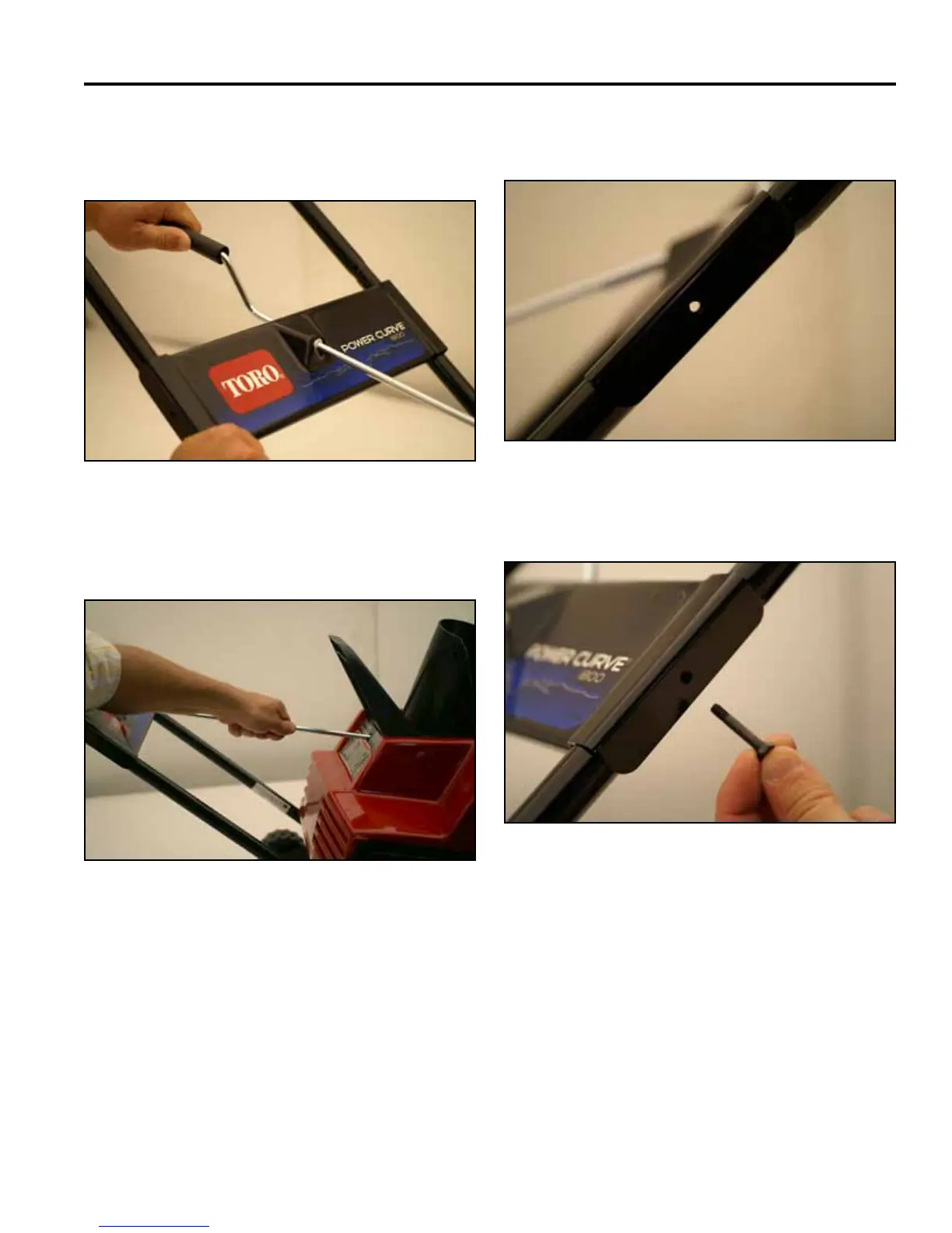
7. Turnthechutecrankrodlightlyuntiltheattened
end drops into the slot in the chute crank gear (Fig.
009).
9. Ensure the mounting plate holes are aligned with the
upper and lower tubing holes (Fig. 011 - LH hole).
8. Firmly push the chute crank rod into the chute crank
gear until it snaps into place (Fig. 010).
10. Insert the LH bolt though the holes (Fig. 012).
Note: Insert the screws from the outside of the
mounting plate. Be careful not to damage the
internal wiring when you insert the screws.
If the wiring blocks the hole, use a blunt
end punch to route the wiring away from the
aligned holes.
Fig. 009 PICT-1444
Fig. 010 PICT-1447a
Fig. 012 PICT-1451
Fig. 011 PICT-1449

 Loading...