Setup
Loose Parts
Use the chart below to verify that all parts have been shipped.
Step
Description
Qty.
Use
Handle
1
Bolt (5/16 x 7/8 inch)
2
Bolt (5/16 x 1-1/2 inches)
2
Washer
4
Locknut (5/16 inch)
4
1
Cable tie
3
Install the handle.
Self-tapping screw
2
2
Fuel tank
1
Install the fuel tank and fuel line.
3
No parts required
–
Fill the crankcase with oil.
Note: Deter mine the left and right sides of the
mac hine from the nor mal operating position.
Step
1
Installing the Handle
Parts needed for this step:
1
Handle
2
Bolt (5/16 x 7/8 inch)
2
Bolt (5/16 x 1-1/2 inches)
4
Washer
4
Locknut (5/16 inch)
3
Cable tie
Procedure
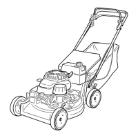
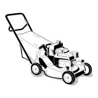
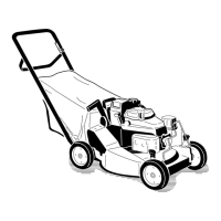
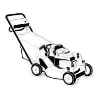
1. Mount the handle to the mo w er housing with
2 bolts (5/16 x 7/8 inc h), 2 bolts(5/16 x 1-1/2
inc hes), 4 w ashers , and 4 loc kn uts ( Figure 3 ).
Figure 3
1. Housing
3. Bolt (5/16 x 1-1/2 inches),
washer, and locknut
2. Handle
4. Bolt (5/16 x 7/8 inch),
washer, and locknut
Note: Install the w ashers with the cup side
facing the handle .
Note: Y ou can adjust the handle height for
more comfor table operation. Securing the
lo w er handle end in the upper hole lo w ers the
handle; securing the lo w er handle end in the
lo w er hole raises the handle .
2. Use the cable ties pro vided to secure the
control cables to the handle .
7