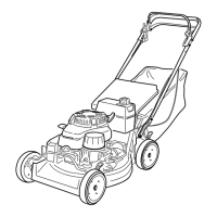
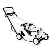
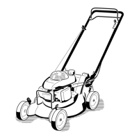
Product Overview
Figure 6
1. Handle
8. Oil ll/dipstick (not shown)
2. Blade control bar 9. Cutting height lever
3. Control bar lock 10. Spark plug
4. Ground speed control lever 11. Air lter
5. Traction control bar 12. Oil lter
6. Fuel tank 13. Grass bag
7. Starter handle 14. Throttle control lever
Controls
T he blade control bar , control bar loc k, g round
speed control lev er , throttle control lev er , and
traction control bar are on the upper handle as
sho wn in ( Figure 7 ).
Figure 7
1. Blade control bar 4. Throttle control lever
2. Control bar lock 5. Traction control bar
3. Ground speed control lever
T he throttle settings are sho wn in ( Figure 8 ).
Figure 8
1. Choke 3. Slow
2. Fast 4. Stop
9