13
4. Align the control panel, side to side, so there is 1/16
in. (2 mm) space between panel and lever.
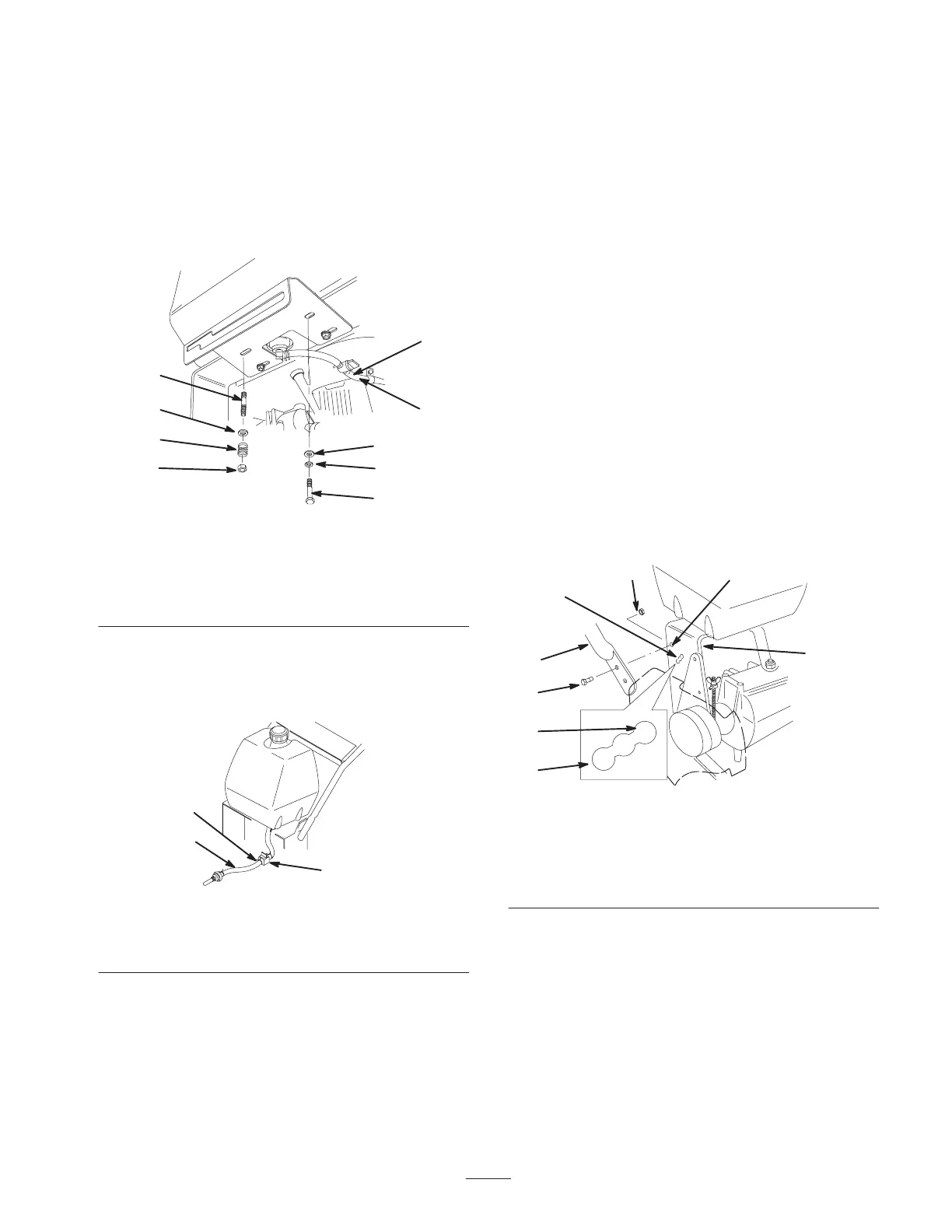
5. Secure the right side control panel and fuel tank to the
rear frame (Fig. 3) with 2 bolts (5/16 x 7/8 in.), lock
washers (5/16 in.) and washers (5/16 in.) (Fig. 3).
6. Secure the left side control panel and fuel tank to the
rear frame (Fig. 3) with 2 studs, washers (5/16 in.),
springs and locknuts (5/16 in.) (Fig. 3).
m–5220
3
8
7
3
6
2
1
5
4
Figure 3
1. Bolt, 5/8 x 7/8 in.
2. Lock washers, 5/16 in.
3. Washer, 5/16 in.
4. Fuel line
5. Hose clamp
6. Stud
7. Spring
8. Locknut
7. Slide the hose clamp onto the fuel line (Fig. 4).
8. Push the fuel line onto the fuel shut off valve and
secure it with a hose clamp (Fig. 4).
1
2
3
m–5183
Figure 4
1. Fuel line
2. Hose clamp
3. Fuel shut off valve
9. Shift lever to second gear and check alignment of
lever in slot of shifter plate. Clearance between top of
lever and the top of the slot should be about equal to
the clearance between bottom of the lever and the
bottom of the slot.
10. If clearance is not correct, remove lever and bend it
slightly to adjust.
Note: Do not bend lever while attached to transmission
shaft or damage may occur.
Install Upper Handle
1. Align upper handle with upper mounting holes in rear
frame (Fig. 5).
2. Secure each upper mounting hole with a flange bolt
(3/8 x 1 in. (26mm)) and flange nut (Fig. 5). Torque
bolts to 25 ft. lbs. (34 N.m).
3. Select high, medium or low position for the lower
mounting hole (Fig. 5). This allows the upper handle
to be adjusted to the user’s height preference.
4. Secure each lower mounting hole with a flange bolt
(3/8 x 1 in. (26mm)) and flange nut (Fig. 5). Torque
bolts to 25 ft. lbs. (34 N.m).
1
2
3
4
8
7
5
6
m–5330
Figure 5
1. Upper handle
2. Rear frame
3. Flange bolt, 3/8 x 1 in.
4. Flange nut, 3/8 in.
5. Upper mounting hole
6. Lower mounting holes
7. Low position
8. High position
Install Control Rods
1. Thread rod fittings equal distance onto each control
rod. For a starting point, thread fittings on
approximately 1–3/4 in. (44 mm) from the start of the
threads (Fig. 6).