Important:Ifthe72inchSideDischargeCutting
Unit,model30368,isbeingmountedtoamodel
30307,30308,30309,30343,30344or30345traction
unitwithaserialnumberpriorto311000301,the
CuttingUnitAlignmentKit,partnumber120–6599
mustbeinstalledtothecuttingunitpriortobeing
mountedtotractionunit.
1
MountingtheGrassDeector
(Model30368only)
Partsneededforthisprocedure:
1
Dischargedeectorassembly(rubber)
1
Screw,5/16x7-1/2inch
1
Spacertube
1Torsionspring
1
Flangenut,5/16
Procedure
WARNING
Anuncovereddischargeopeningcouldallowthe
lawnmowertothrowobjectsintheoperator’sor
bystander’sdirectionandresultinseriousinjury.
Also,contactwiththebladecouldoccur.
•Neveroperatethelawnmowerunlessyouinstall
acoverplate,amulchplate,oragrasschuteand
catcher.
•Makesurethegrassdeectorisinthedown
position.
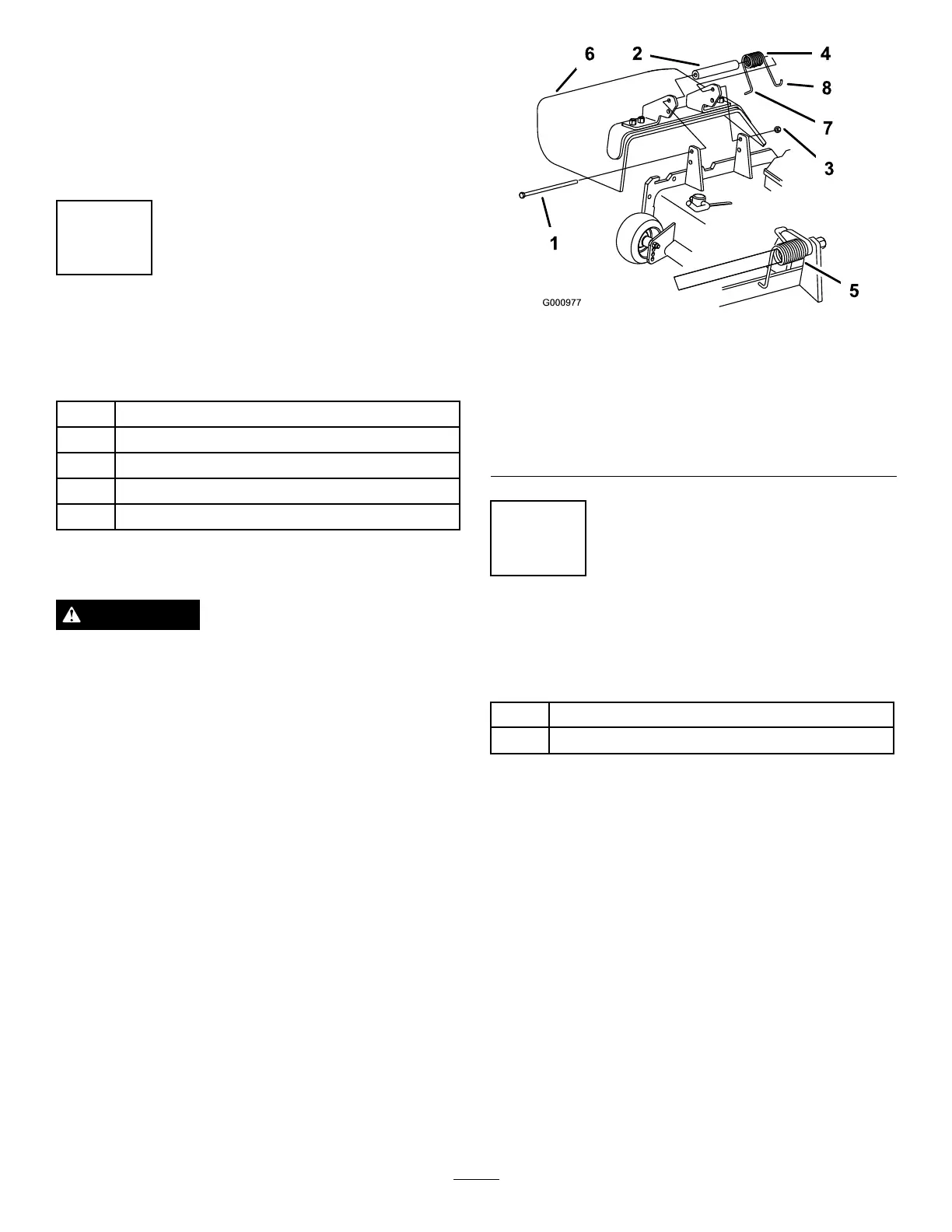
1.Placethespacerandspringbetweenthegrass
deectorbrackets(Figure2).PlacethelefthandJ
hookendofspringbehinddeckedge.
Note:MakesurethelefthandJhookendofthe
springisinstalledbehindthedeckedgebefore
installingtheboltasshowninFigure2.
2.Installtheboltandnut.PlacetherighthandJ
hookendofthespringaroundthegrassdeector
(Figure2).
Important:Thegrassdeectormustbeableto
lowerdownintoposition.Liftthedeectorup
totestthatitlowersintothefulldownposition.
Figure2
1.Bolt
5.Springinstalled
2.Spacer6.GrassDeector
3.Locknut
7.Lefthandhookendof
spring,placebehinddeck
edgebeforeinstallingbolt
4.Spring8.Righthandhookendof
spring
2
InstallingtheLiftArmstothe
TractionUnit
Partsneededforthisprocedure:
2Pivotpinassembly
2
Cotterpin
Procedure
1.Ononesideofthetractionunit,loosen(donot
remove)thewheelnutssecuringthewheelandtire
assemblytothefrontwheelstuds.
2.Jackupthemachineuntilthefrontwheelisoffof
theoor.Usejackstandsorblockthemachineto
preventitfromaccidentallyfalling.
3.Removethewheelnutsandslidethewheelandtire
assemblyoffofthestuds.
4.Mountaliftarmtothepivotbracketwithapivotpin
andacotterpin(
Figure3).Mounttheliftarmwith
thebendpositionedoutward.
5.Hookthebrakereturnspringtothetabonthelift
arm(Figure3).
9