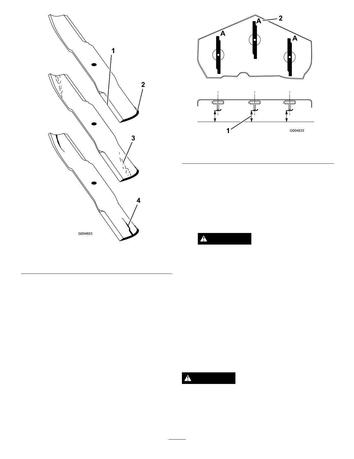
Figure65
1.CuttingEdge3.Wear/slotForming
2.SailArea4.Crack
CheckingforBentBlades
1.DisengagethePTO,releasethetractionpedalandset
theparkingbrake.
2.MovethethrottlelevertotheSlowposition,stopthe
engine,removethekey,andwaitforallmovingpartsto
stopbeforeleavingtheoperatingposition.
3.Rotatethebladesuntiltheendsfaceforwardand
backward(
Figure66).Measurefromalevelsurfaceto
thecuttingedge,positionA,oftheblades(Figure66).
Notethisdimension.
Figure66
1.Measureherefromblade
tohardsurface
2.PositionA
4.Rotatetheoppositeendsofthebladesforward.
5.Measurefromalevelsurfacetothecuttingedgeof
thebladesatthesamepositionasinstep3above.
Thedifferencebetweenthedimensionsobtainedin
steps3and4mustnotexceed3mm(1/8inch).Ifthis
dimensionexceeds3mm(1/8inch),thebladeisbent
andmustbereplaced;refertoRemovingtheBlades
andInstallingtheBlades.
WARNING
Abladethatisbentordamagedcouldbreak
apartandcouldseriouslyinjureorkillyouor
bystanders.
•Alwaysreplacebentordamagedblade
withanewblade.
•Neverleorcreatesharpnotchesinthe
edgesorsurfacesofblade.
RemovingtheBlades
Bladesmustbereplacedifasolidobjectishit,ifthebladeis
outofbalanceorisbent.Toensureoptimumperformance
andcontinuedsafetyconformanceofthemachine,use
genuineTororeplacementblades.Replacementbladesmade
byothermanufacturersmayresultinnon-conformancewith
safetystandards.
WARNING
Contactwithasharpbladecancauseseriousinjury.
Wearglovesorwrapsharpedgesofthebladewith
arag.
1.Holdthebladeendusingaragorthickly-paddedglove.
57