installed)andtheremainingspacersontothe
spindleshaft.Installthetensioningcapto
securetheassembly.
5.Removethehairpincotterandclevispin
securingtheheight-of-cutchainstotherearof
thecuttingunit(Figure20).
g011596
Figure20
1.Height-of-cutchain2.Clevispinandhairpin
cotter
6.Mounttheheight-of-cutchainstothedesired
height-of-cuthole(Figure21)withtheclevispin
andhairpincotter.
decal100-5624nc
Figure21
Note:Whenusing25mm(1inch),38mm
(1-1/2inch),oroccasionally51mm(2inch)
height-of-cut,movetheskidsandgagewheels
tothehighestposition.
SideCuttingUnits
Toadjusttheheight-of-cutonthesidecuttingunits,
addorremoveanequalnumberofspacersfromthe
castorforks,positionthecastorwheelaxlesinthe
highorlowheight-of-cutholesinthecastorforks,and
securethepivotarmstotheselectedheight-of-cut
bracketholes.
1.Positionthecastorwheelaxlesinthesame
holesinallofthecastorforks(Figure22and
Figure24).Refertothefollowingchartto
determinethecorrectholeforthesetting.
2.Removethetensioningcapfromthespindle
shaft(Figure22)andslidethespindleoutof
castorarm.Putthetwoshims(3mm[1/8
inch])ontospindleshaftastheywereoriginally
installed.Theseshimsarerequiredtoachieve
alevelacrosstheentirewidthofthecutting
units.Slidetheappropriatenumberof13mm
(1/2inch)spacersontothespindleshafttoget
thedesiredheight-of-cut;thenslidethewasher
ontotheshaft.
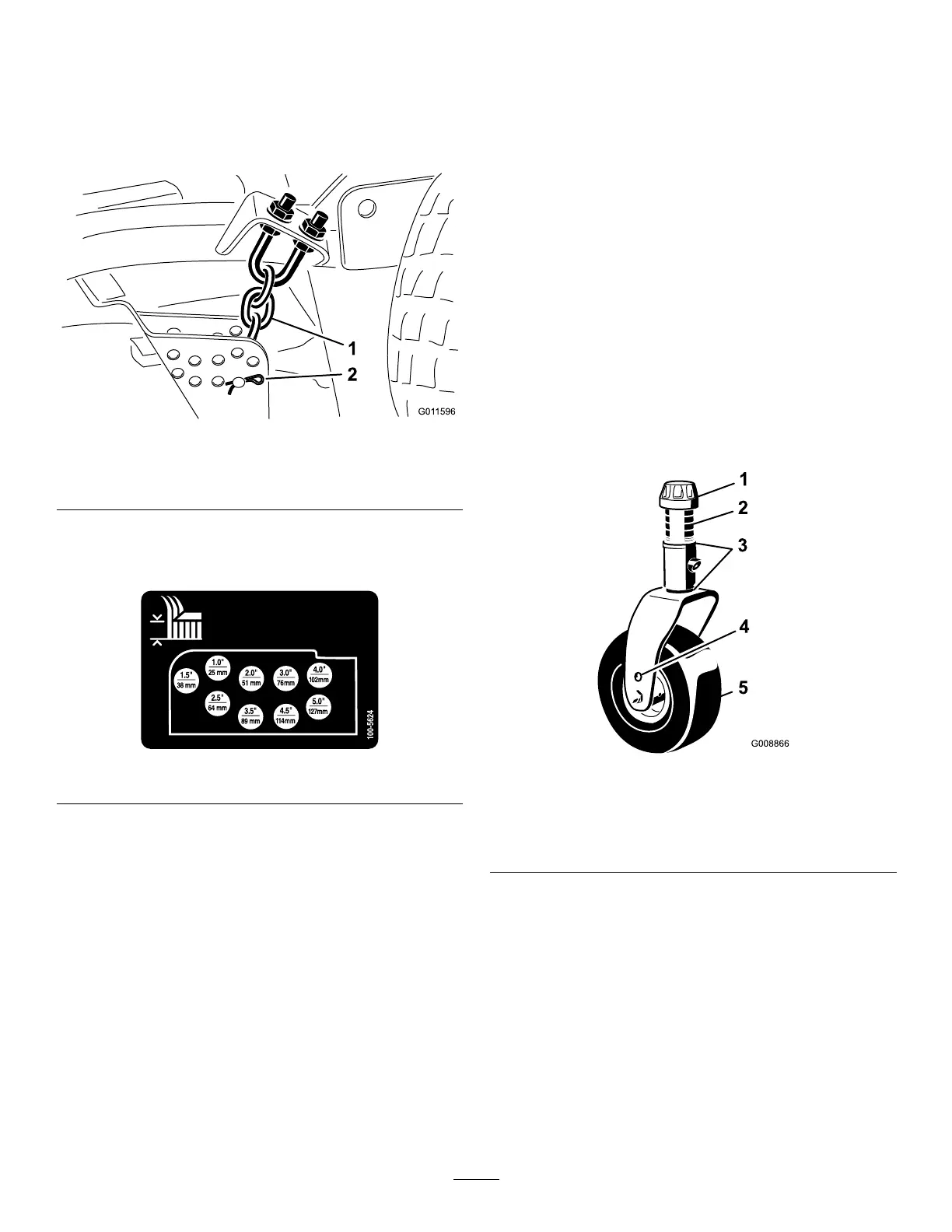
g008866
Figure22
1.Tensioningcap4.Toaxlemountinghole
2.Spacers5.Castorwheel
3.Shims
Refertothefollowingcharttodeterminethe
combinationsofspacersforthesetting.
30