burnmarksandcracks.Replacethebeltifanyof
theseconditionsareevident.
1.Lowerthecuttingunittotheshopoor.Remove
thebeltcoversfromthetopofthecuttingunit
andsetthecoversaside.
2.Loosentheeyeboltallowingtheremovalofthe
extensionspring(Figure97).
3.Loosentheangenutsecuringthestopbolt
tothemountingtab.Backoffthenutenough
toallowtheidlerarmtopassbythestopbolt
(Figure97).Movetheidlerpulleyawayfromthe
belttoreleasebelttension.
Note:Ifthestopboltiseverremovedfromthe
mountingtab,makesureitisreinstalledinthe
holethatalignsthestopboltheadwiththeidler
arm.
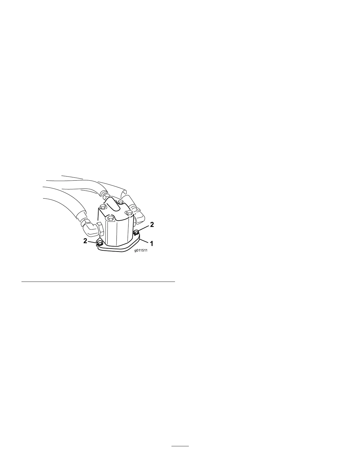
4.Removetheboltssecuringthehydraulicmotor
tothecuttingunit(Figure98).Liftthemotoroff
ofthecuttingunitandlayitontopofthecutting
unit.
g011511
Figure98
1.Hydraulicmotor2.Mountingbolts
5.Removetheoldbeltfromaroundthespindle
pulleysandidlerpulley.
6.Routethenewbeltaroundthespindlepulleys
andidlerpulleyassembly.
7.Positionthehydraulicmotoronthecutting
unitafterroutingthebeltaroundthepulleys.
Mountthemotortothecuttingunitwiththebolts
previouslyremoved.
Note:Makesurethebeltispositionedonthe
springsideofthebeltguide(Figure97).
8.Reconnecttheextensionspring(Figure97)to
theeyeboltandtensionthebeltasfollows:
•Whenproperlytensioned,theextension
spring(hooktohook)measurementshould
beapproximately8.9cm±.63cm(3.50±.25
inch(inside).
•Oncethecorrectspringtensionisattained,
adjustthestopbolt(carriagebolt)untilthere
isapproximately.32cm±.152/.000cm(.125
+.060/-.000inch)clearancebetweenthe
headoftheboltandtheidlerarm.
64