Figure16
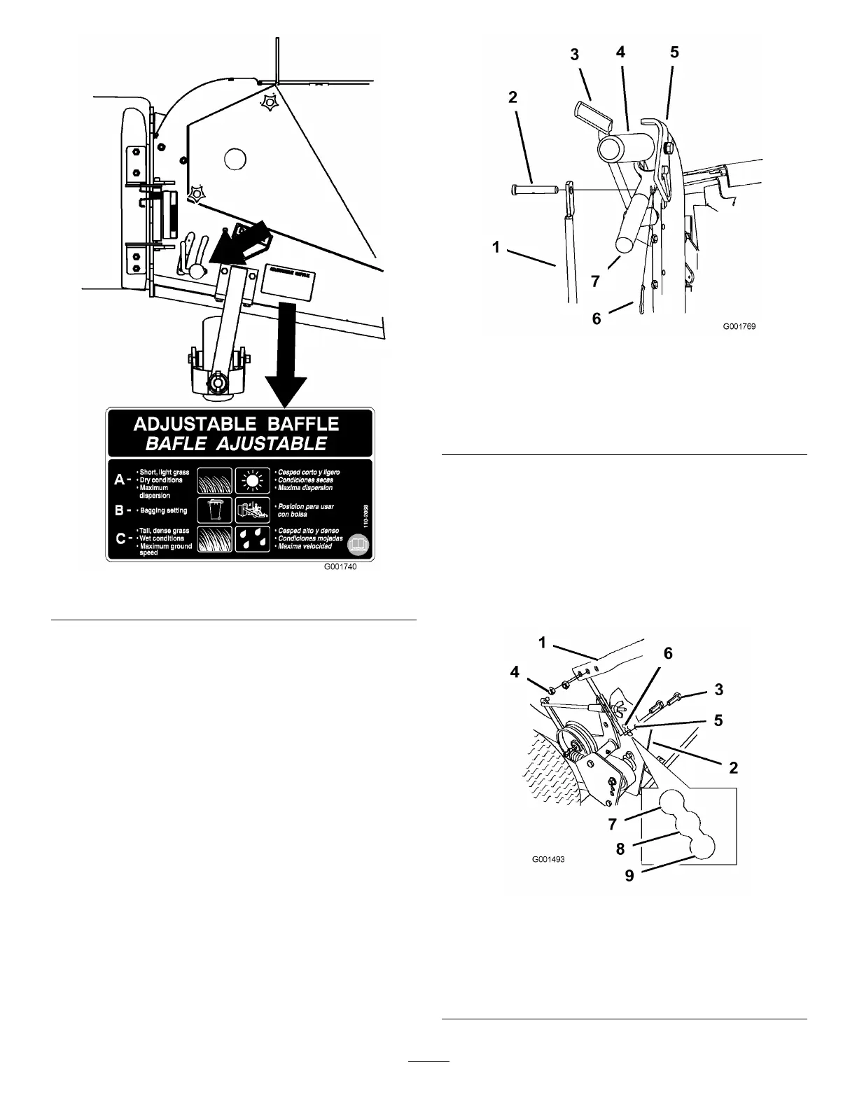
AdjustingtheHandleHeight
Thehandlepositioncanbeadjustedtomatchthe
operator’sheightpreference.
1.Removethehairpincotterpinsandclevispinsfrom
thedriveleversandneutrallocks(Figure17).
Figure17
1.Controlrod
5.Neutrallock
2.Clevispin
6.Hairpincotterpin
3.OperatorPresence
Controllever(OPC)
7.Lefthandleshown
4.Handle8.Drivelever
2.Loosentheupperbolts(3/8x1-1/4inch)and
angenutsecuringhandletorearframe(Figure18).
3.Removethelowerbolts(3/8x1inch)andange
nutssecuringhandletorearframe(Figure18).
4.Pivothandletodesiredoperatingpositionand
installlowerangebolts(3/8x1inch)andange
nutsintomountingholes.Tightenallangebolts.
Figure18
1.Upperhandle6.Lowermountingholes
2.Rearframe
7.Lowposition
3.Flangebolt(3/8x1inch)
8.Middleposition
4.Locknut(3/8inch)
9.Highposition
5.Uppermountinghole
22