8
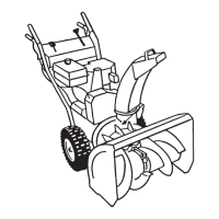
Assembly
Note: Determine the left and right sides of the machine from the normal operating position.
Loose Parts
DESCRIPTION QTY. USE
Handle assembly 1
Bolts 4
Installing the handle assembly
Curved washers 4
Speed selector rod 1
Cotter pin 1
Installing the speed selector rod
Flat washer 1
Spring 1
Installing the traction rod
Flange locknut 1
Installing the traction rod
Lower link 1
Flange nut 1 Installing the auger/impeller drive control
linkage
Flange locknut 1
Discharge chute 1 Installing the discharge chute
Chute control rod assembly (Rod and bracket,
worm gear, and bracket)
1
Bolt, pyramidal washer, and locknut 1 Installing the chute control rod
Bolt 1
Locknut 1
Ignition key 1 Starting and stopping the engine
Installing the Handle Assembly
1. Remove the tie straps that secure the control rods to the
handle assembly.
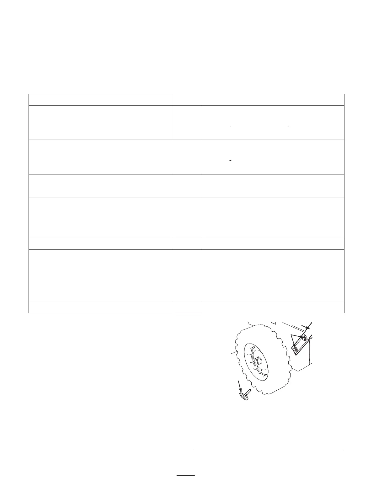
2. Remove the axle pins from both wheels (Fig. 3) and
slide the wheels outward on the axle approximately one
inch (2.5 centimeters).
1
2
3
653
Figure 3
1. Axle pin (2)
2. Bolts and curved
washers (4)
3. Handle assembly