9
1
2
3
653
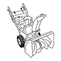
Figure 2
1. Axle pin (2)
2. Cap screws and curved
washers (4)
3. Handle assembly
3. Thread a flange nut (not the flange locknut) with the
flange down onto the traction rod attached to the left
side of the handle assembly (Fig. 3).
654
1
2
3
4
5
Figure 3
1. Lower traction rod
2. Traction rod
3. Flange nut
4. Loop
5. Flange locknut
4. Position the left side of the handle assembly against the
side of the snowthrower and insert the end of the
traction rod through the loop in the lower traction rod
(Fig. 3).
5. Align the holes in the left side of the handle assembly
with the holes in the left side plate, and secure the
handle with two cap screws and curved washers until
they are finger tight (Fig. 2).
Note: The concave side of the curved washer goes
against the outside of the handle.
6. Align the holes in the right side of the handle assembly
with the holes in the right side plate, and secure the
handle with two cap screws and curved washers until
they are finger tight.
7. Ensure that the handles are at the same height, then
tighten the handle fasteners securely.
8. Slide the wheels inward and insert each axle pin
through the hole in each wheel hub and through the
inner hole of the axle (Fig. 4).
1
3
2
473
Figure 4
1. Inner axle hole and wheel
hub
2. Outer axle hole
3. Axle pin
Note: To use tire chains (optional), install the axle pins
through the outer axle holes.
Installing the Speed Selector
Rod
1. Pull the speed selector arm (Fig. 5) to the most outward
position.
648
2
3
1
Figure 5
1. Speed selector arm
2. Flat washer and cotter pin
3. Speed selector rod
2. Move the speed selector (Fig. 13) on the control panel
to the R (Reverse) position.
3. Install the speed selector rod into the selector arm, add a
flat washer on the selector rod, and secure it with a
cotter pin (Fig. 5).
Installing the Traction Rod
1. Thread the flange locknut (flange side up) onto the
bottom of the traction control rod, below the loop in the
lower traction rod (Fig. 3).
2. Adjust the two flange nuts up or down on the traction
rod until the distance between the top of the handgrip
and the bottom of the traction control lever is
approximately 4-3/8 inches (11 centimeters) as shown
in Figure 6.