Note:Ensurethatagapof1/16to1/8inch(2to
3mm)existsbetweenthecontrolbarandthehandle
(Figure8).
Important:Thecontrolcablemustcontainsome
slackwhenyoudisengagethecontrolbarforthe
rotorbladestostopproperly.
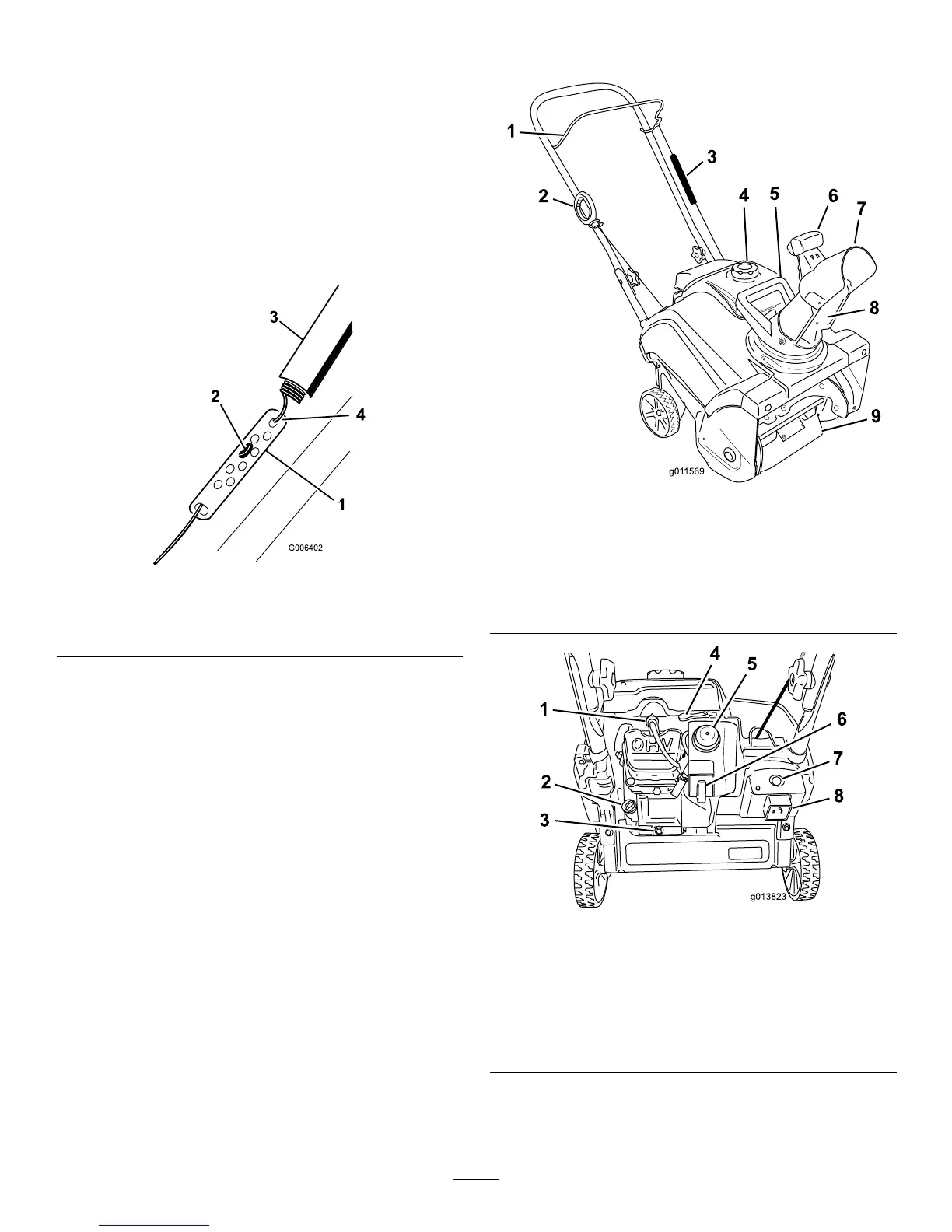
AdjustingtheControlCable
1.Slideupthespringcoverandunhookthespring
fromtheadjusterlink(
Figure9).
Figure9
1.Adjusterlink
3.Springcover
2.Z-tting
4.Unhookthespringhere.
Note:Youcanpulluptheadjusterlinkandcableto
makeunhookingthespringeasier.
2.MovetheZ-ttingtoahigherorlowerholeonthe
adjusterlinkasneededtoobtainthe1/16-inchto
1/8-inch(2mmto3mm)gapbetweenthecontrol
barandthehandle(
Figure9).
Note:MovingtheZ-ttinghigherdecreasesthe
gapbetweenthecontrolbarandthehandle;moving
itlowerincreasesthegap.
3.Hookthespringtotheadjusterlinkandslidethe
springcoverovertheadjusterlink.
4.Checktheadjustment;refertoCheckingtheControl
Cable.
Note:Thebeltmayslip(squeal)inwetconditions;
todryoutthedrivesystem,starttherotorandrun
itwithoutaloadfor30seconds.
ProductOverview
Figure10
1.Controlbar6.Chutedeectortrigger
2.Recoilstarthandle
7.Chutedeector
3.Springcover
8.Dischargechute
4.Fueltankcap9.Rotorblades
5.Chutehandle
Figure11
1.Sparkplug
5.Primer
2.Oilllcap
6.Ignitionkey
3.Oildrainplug
7.Electric-startbutton
(model38282only)
4.Chokelever8.Plug-inforelectricstart
(model38282only)
8