14
Setup
Loose Parts
Note: Use the chart below to verify all parts have been shipped.
Description Qty. Use
Rear Wheels 2 Installing the drive wheels
Retaining rod
Bolt, 5/16 x 1 inch
Locknut, 5/16 inch
1
1
1
Installing the seat retaining rod
Control lever–right
Control lever–left
Bolt, 3/8 x 1 inch
Spring washer, 3/8 inch
1
1
4
4
Installing the motion control levers
Key
Operator’s Manual
Engine Operator’s Manual
Parts Catalog
2
1
1
1
Read before operating machine
Registration card 1 Fill out and return to Toro
Installing the Drive Wheels
1. Uncrate mower.
1. Remove wheel bolts or nuts from rear wheel hubs.
2. Align holes. Mount drive wheels with the valve stem
to the outside of the traction unit.
3. Secure using wheel bolts or nuts provided. Torque to
95 ft-lb (128 NM).
Important Make sure that wheel nuts are torqued to
95 ft–lb (128 NM).
Tire Pressure
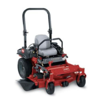
Check the air pressure in the front and rear tires (Fig. 2).
Pressure: 13 psi (90 kPa)
1
m–1872
Figure 2
1. Valve stem
Installing the Seat Retaining
Rod
1. Tilt seat up. Remove the locknut (5/16 inch) from bolt
attaching seat retaining rod to seat frame (Fig. 3).
2. Remove retaining rod from seat and insert the L
shaped end of the rod into the hole directly above the
left–side hydraulic pump (Fig. 3).