22
1
m–4122
3
2
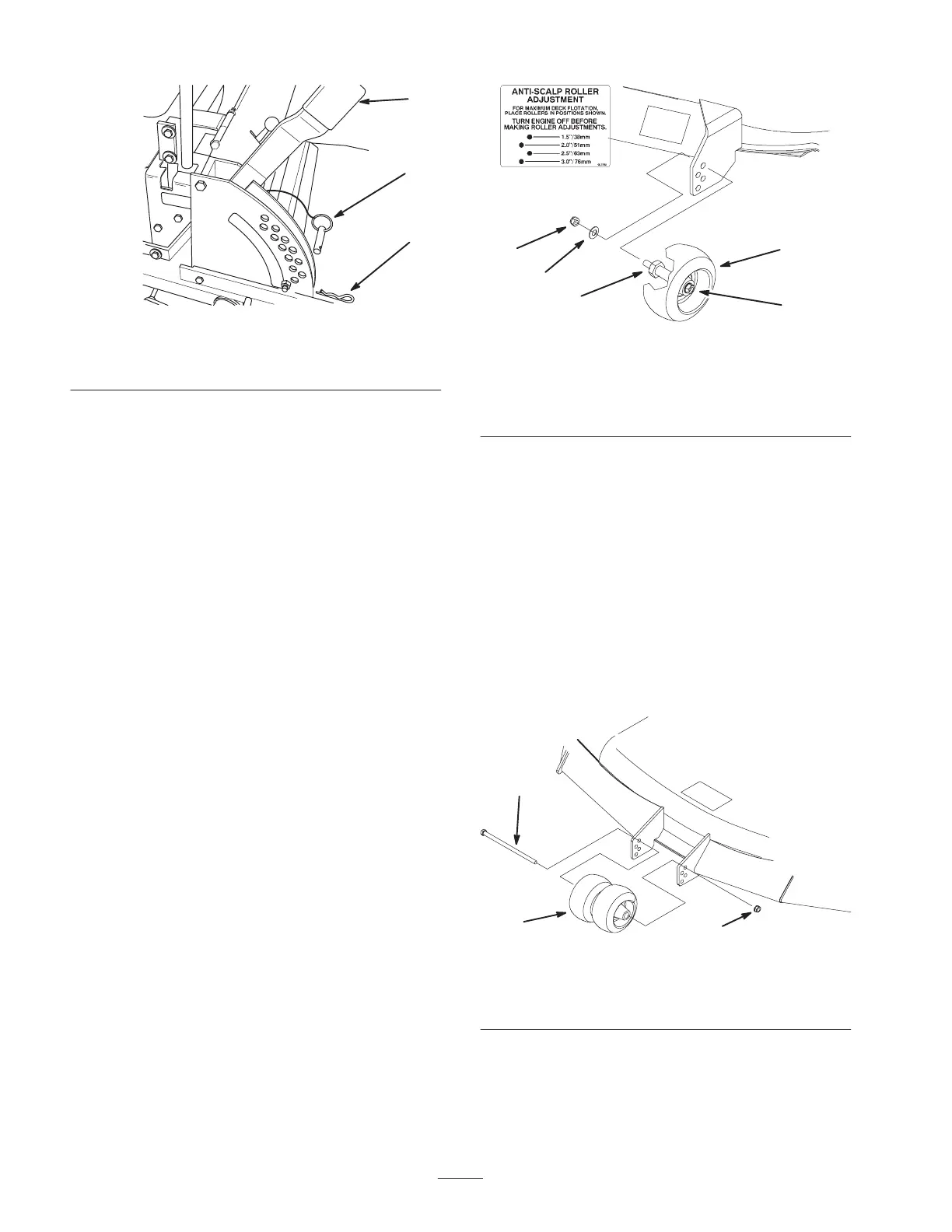
Figure 20
1. Height-of-cut lever
2. Clevis pin
3. Hairpin cotter
5. Lower height–of–cut lever onto clevis pin.
Adjusting Anti-Scalp Rollers
Whenever you change the height-of-cut it is
recommended to adjust the height of the anti-scalp rollers.
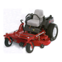
Adjusting the Outside Rollers
1. Disengage the power take off (PTO) and turn the
ignition key to off. Move controllers to neutral locked
position and apply parking brake. Remove the key.
2. After adjusting height-of-cut remove nut and washer
while holding stud with wrench (Fig. 21).
Note: Do not remove the wheel nut and washer (Fig. 21).
3. Select hole so gage wheel is positioned to the nearest
corresponding height-of-cut desired (Fig. 21).
4. Reinstall the flange nut and spring disk. Torque to
40–45 ft-lb (54.2–61.0 Nm) (Fig. 21).
5. Repeat adjustment on other gage wheels.
m–4167
1
2
3
4
5
1
Figure 21
1. Gage wheel
2. Stud
3. Washer
4. Nut
5. Wheel nut and washer.
Do not remove.
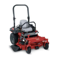
Adjusting the Center Rollers
1. Disengage the power take off (PTO) and turn the
ignition key to off. Move controllers to neutral locked
position and apply parking brake.
2. After adjusting height-of-cut, remove bolt and nut
(Fig. 22).
3. Select hole so gage wheel is positioned to the nearest
corresponding height-of-cut desired (Fig. 22).
Note: Do not adjust rollers to support the deck.
4. Reinstall the bolt, center rollers and nut (Fig. 22).
m–4124
1
2
3
Figure 22
1. Center rollers and spacer
2. Nut
3. Bolt