49
1
2
M–4417
3
1
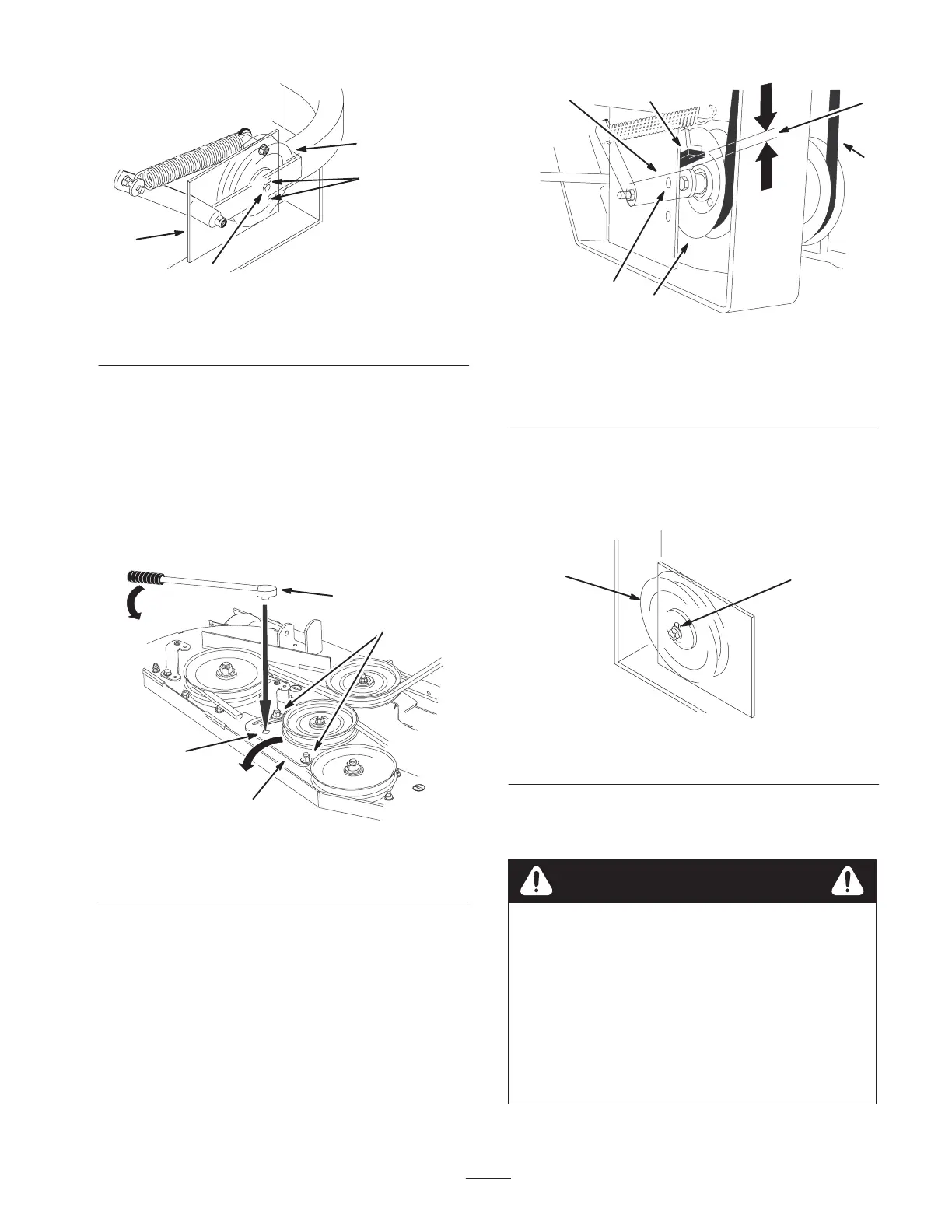
Figure 71
1. Center bolt
2. Alignment hole
3. Left support plate
4. Spring loaded idler
5. If adjustment is required, loosen the mower idler plate
and adjust it (Fig. 72).
6. Insert a ratchet or breaker bar into the square hole in
the mower idler plate to adjust the tension (Fig. 72).
7. To increase belt tension, rotate the mower idler plate
until resistance is felt and rotation stops. Do not go
past when it stops (Fig. 72).
8. Tighten the idler plate bolts (Fig. 72).
2
m–6826
1
3
4
Figure 72
1. Mower idler plate
2. Square hole
3. Ratchet or breaker bar
4. Idler plate bolt
9. Check the distance from the rubber stop and the arm of
the spring loaded idler pulley when the idler plate is
tightened. It needs to be 0 to 1/4 inch (0 to 6 mm)
from the rubber stop (Fig. 73).
10. Adjust the belt tension and the idler plate, if necessary,
and tighten all hardware securely (Fig. 72).
m–6825 1
2
3
5
4
6
Figure 73
1. Spring loaded idler pulley
2. Top alignment hole
3. 0 to 1/4 inch gap
(0 to 6 mm)
4. Idler pulley arm
5. Belt
6. Rubber bumper
11. If the mower idler plate contacts the end of the
adjustment slot and more belt tension is required, a
small change to the right side fixed idler can create
more belt tension adjustment (Fig. 74).
m–3746
12
Figure 74
1. Fixed Idler 2. Adjustment slot
Replacing the Grass Deflector
An uncovered discharge opening could allow the
lawn mower to throw objects in the operator’s or
bystander’s direction and result in serious injury.
Also, contact with the blade could occur.
• Never operate the lawn mower unless you
install a cover plate, a mulch plate, or a grass
chute and catcher.
• Make sure the grass deflector is in the
down position.
Warning