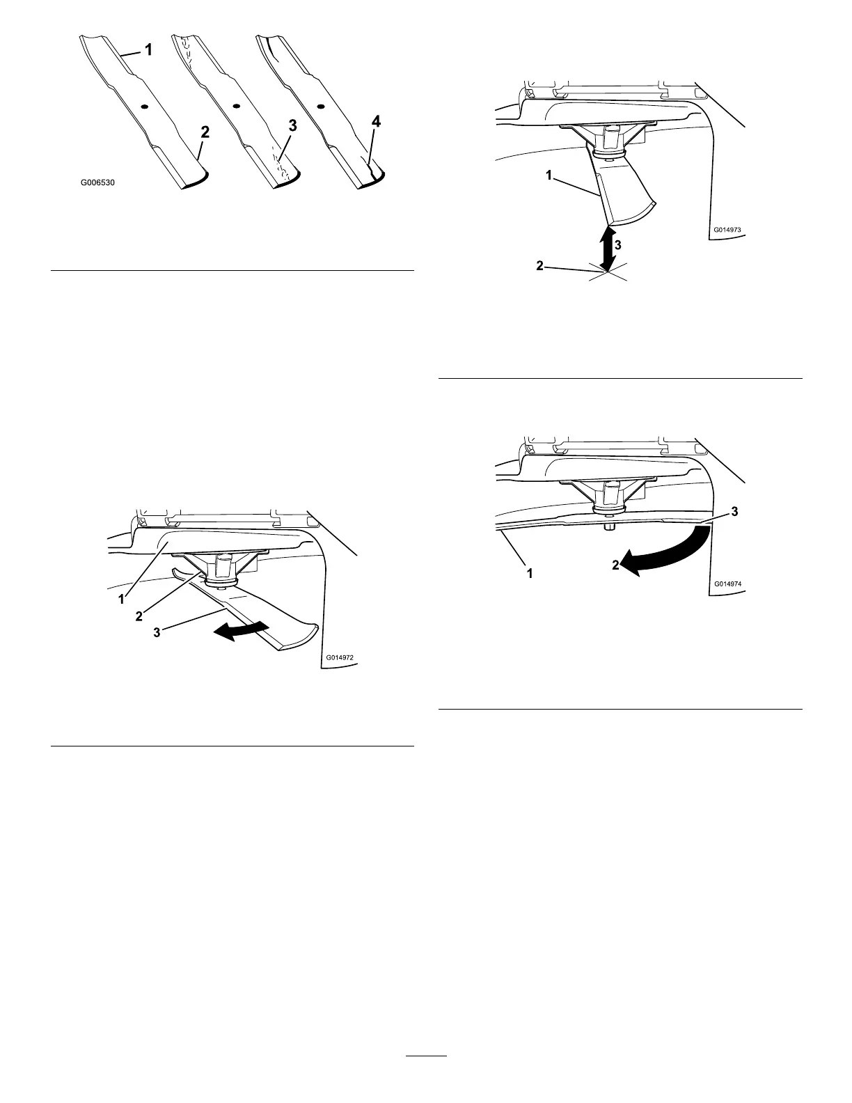
Figure40
1.Cuttingedge3.Wear/slotforming
2.Curvedarea
4.Damage
CheckingforBentBlades
Note:Themachinemustbeonalevelsurfaceforthe
followingprocedure.
1.Raisethemowerdecktothehighestheight-of-cut
position;alsoconsideredthe'transport'position.
2.Whilewearingthicklypaddedgloves,orotheradequate
handprotection,slowlyrotatethebladetobemeasure
intoapositionthatallowseffectivemeasurementofthe
distancebetweenthecuttingedgeandthelevelsurface
themachineison(Figure41).
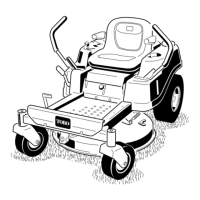
Figure41
1.Deck3.Blade
2.Spindlehousing
3.Measurefromthetipofthebladetotheatsurface
(Figure42).
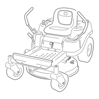
Figure42
1.Blade(inpositionformeasuring)
2.Levelsurface
3.Measureddistancebetweenbladeandthesurface(A)
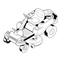
4.Rotatethesameblade180degrees,sothattheopposing
cuttingedgeisnowinthesameposition(
Figure43).
Figure43
1.Blade(sidepreviouslymeasured)
2.Measurement(positionusedpreviously)
3.Opposingsideofbladebeingmovedintomeasurement
position
5.Measurefromthetipofthebladetotheatsurface
(Figure44).
Note:Thevarianceshouldbenomorethan3mm
(1/8inch).
32