2.Installthebladestiffener,thecurvedwasher(cupped
sidetowardtheblade),andthebladebolt(Figure45).
3.Torquethebladeboltto47to88N-m(35to65ft-lb).
LevelingtheMowerDeck
Checktoensurethatthemowerdeckislevelanytimeyou
installthemowerorwhenyouseeanunevencutonyour
lawn.
Themowerdeckmustbecheckedforbentbladespriorto
leveling;anybentbladesmustberemovedandreplaced;refer
to
CheckingforBentBlades(page32)beforecontinuing.
Themowerdeckmustbeleveledside-to-siderstthenthe
fronttorearslopecanbeadjusted.
Requirements:
•Themachinemustbeonalevelsurface.
•All4tiresmustbeproperlyinated;referto
Checking
theTirePressure(page30).
Side-to-SideLeveling
1.Parkthemachineonalevelsurfaceanddisengagethe
blade-controlswitch.
2.Movethemotion-controlleversoutwardtothepark
position,stoptheengine,removethekey,andwaitfor
allmovingpartstostopbeforeleavingtheoperating
position.
3.Settheheight-of-cutlevertomiddleposition.
4.Carefullyrotatethebladessothattheyareallsideto
side(Figure48andFigure49).
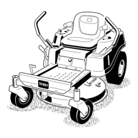
Figure48
Mowerdeckswith2blades
1.Bladessidetoside
3.Outsidecuttingedges
2.Sailareaofblade4.Measurefromthetipofthe
bladetotheatsurface
here
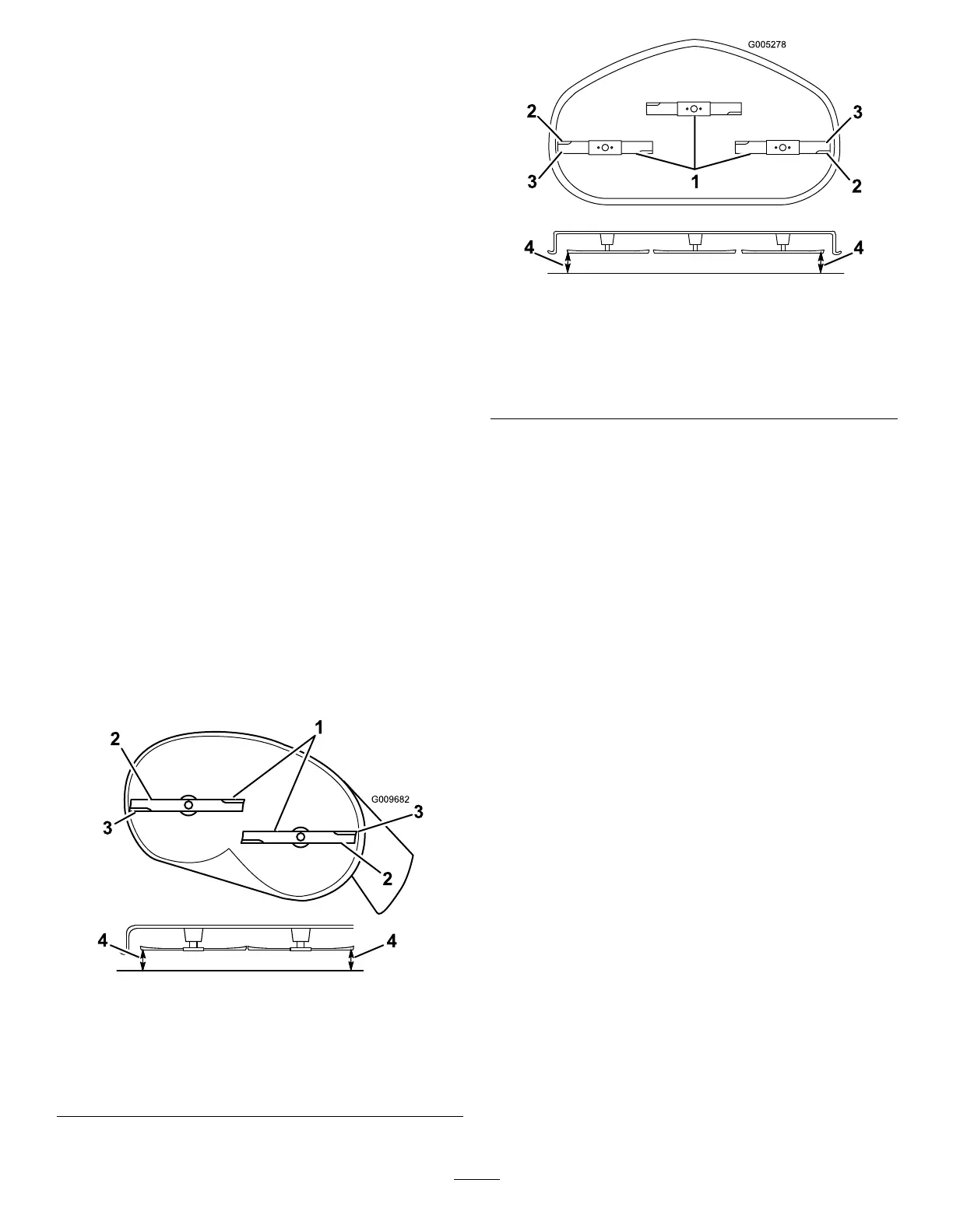
Figure49
MowerDeckswith3Blades
1.Bladessidetoside
3.Outsidecuttingedges
2.Sailareaofblade4.Measurefromthetipofthe
bladetotheatsurface
here
5.Measurebetweentheoutsidecuttingedgesandtheat
surface(Figure48andFigure49).
Note:Ifbothmeasurementsarenotwithin5mm
(3/16inch),anadjustmentisrequired;continuewith
thisprocedure.
6.Supporttheweightofmowerdeckbyplacingwood
blocksundertheedgesofthemowerdeck.
Note:Avoidplacingthesupportsunderanyanti-scalp
rollersifpresentonthemowerdeck.
7.Movetotheleftsideofthemachine.
Note:Checkifthesidecarriageboltisinthexedor
slottedposition(Figure50).
8.Ifthesidecarriageboltisinthexedposition,remove
thesidecarriageboltandsidelockingnutfromthe
xedpositionandinstallitintotheslottedadjustment
position(Figure50).
Note:Iftheboltisintheslottedposition,thecarriage
boltandthesidelockingnutrequirenoremoval.
34