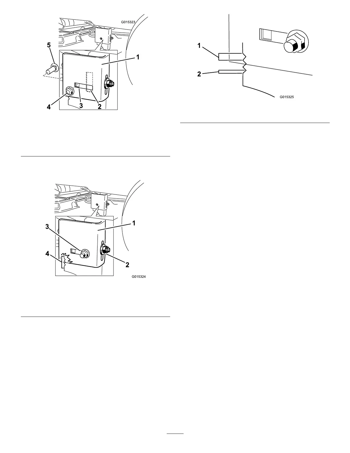
Figure50
1.Hangerbracket
4.Sidelockingnut.
2.Slottedadjustment
position
5.Sidecarriagebolt
3.Fixedposition
9.Loosentherearlockingnutonthehangerbracket
(Figure51).
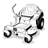
Figure51
1.Hangerbracket
3.Sidelockingnut,slotted
position.
2.Rearlockingnut4.Adjustmentnotches
10.Loosenthesidelockingnutonthehangerbracketjust
enoughtoallowthehangertobeadjusted(Figure51).
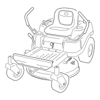
Usethenotchesontheweldedbrackettomeasure
theamountofadjustment.Eachnotchsurfaceis
equivalentto6.35mm(1/4inch),whileasinglesideis
3.18mm(1/8inch)asshownin
Figure52).
11.Adjusttheheightofthemowerdecktothedesired
height.
Figure52
1.0.25inch2.0.125inch
12.Stopthedeckattheadjustedpositionandtightenthe
sidelockingnutonthehangerbrackettoholdthenew
position(Figure51).
13.Tightentherearlockingnutonthehangerbracket.
14.Continuelevelingthedeckbycheckingthefront-to-rear
bladeslope;refertoAdjustingtheFront-to-RearBlade
Slope(page35).
AdjustingtheFront-to-RearBlade
Slope
Checkthefront-to-rearbladelevelanytimeyouinstallthe
mower.Ifthefrontofthemowerismorethan7.9mm
(5/16inch)lowerthantherearofthemower,adjusttheblade
levelusingthefollowinginstructions:
1.Parkthemachineonalevelsurfaceanddisengagethe
blade-controlswitch.
2.Movethemotion-controlleversoutwardtothepark
position,stoptheengine,removethekey,andwaitfor
allmovingpartstostopbeforeleavingtheoperating
position.
3.Settheheight-of-cutlevertomiddleposition.
Note:Checkandadjusttheside-to-sidebladelevelif
youhavenotcheckedthesetting;refertoSide-to-Side
Leveling(page34).
4.Carefullyrotatethebladessotheyarefacingfrontto
rear(Figure53andFigure54).
35