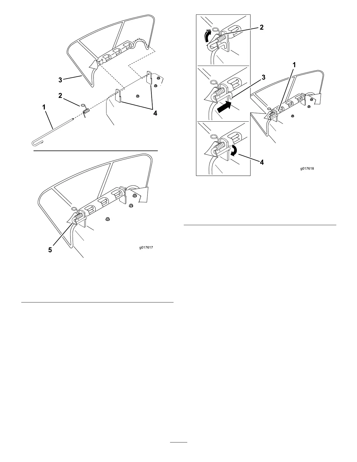
Figure58
1.Rod4.Deckbrackets
2.Spring5.Springinstalledoverthe
rod
3.Deector
2.Positionthenewdischargedeectorwiththebracket
endsbetweentheweldedbracketsonthedeckas
showninFigure58.
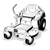
3.Installthespringontothestraightendoftherod.
Note:Positionthespringontherodasshowninso
theshorterspringendiscomingfromundertherod
beforethebendandgoingovertherodasitreturns
fromthebend.
4.Lifttheloopendofthespringandplaceitintothe
notchonthedeectorbracket(
Figure59).
Figure59
1.Rodandspringassembly
installed
3.Rod,shortend,moved
behindmowerbracket
2.Loopendofthespring
installedintothenotchin
thedeectorbracket
4.Shortend,retainedbythe
mowerbracket
5.Securetherodandspringassemblybytwistingitsothe
shortendoftherodcanbeplacedbehindthefront
bracketweldedtothedeck(Figure59).
Important:Thegrassdeectormustbespring
loadedinthedownposition.Liftthedeectorup
totestthatitsnapstothefulldownposition.
38