g006530
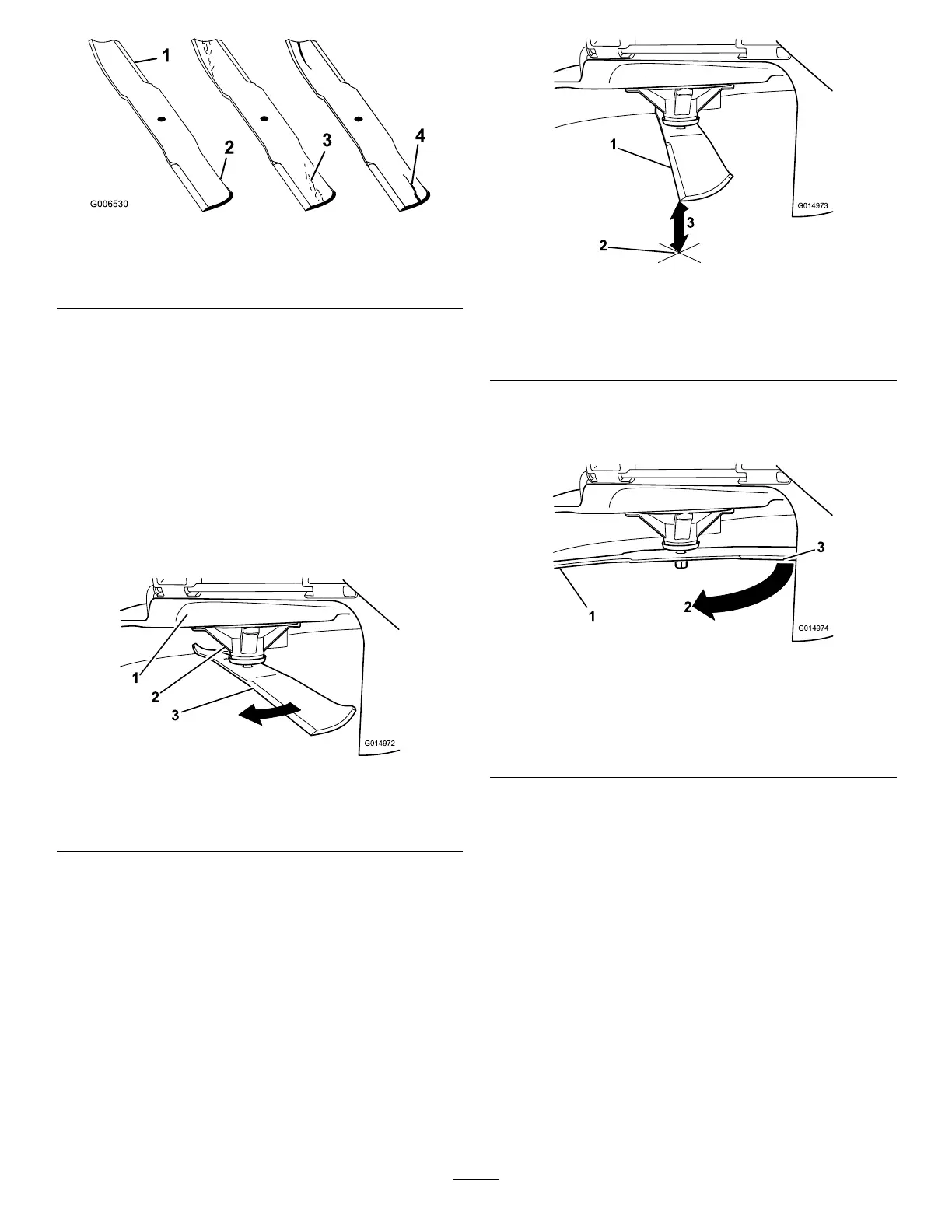
Figure59
1.Cuttingedge3.Wear/slotforming
2.Curvedarea4.Crack
CheckingforBentBlades
Note:Themachinemustbeonalevelsurfacefor
thefollowingprocedure.
1.Raisethemowerdecktothehighest
height-of-cutposition.
2.Whilewearingthicklypaddedgloves,orother
adequatehandprotection,slowlyrotatethe
bladeintoapositionthatallowsyoutomeasure
thedistancebetweenthecuttingedgeandthe
levelsurfacethemachineison(Figure60).
g014972
Figure60
1.Deck3.Blade
2.Spindlehousing
3.Measurefromthetipofthebladetotheat
surface(Figure61).
g014973
Figure61
1.Blade(inpositionformeasuring)
2.Levelsurface
3.Measureddistancebetweenbladeandthesurface(A)
4.Rotatethesameblade180degreessothat
theopposingcuttingedgeisnowinthesame
position(Figure62).
g014974
Figure62
1.Blade(sidepreviouslymeasured)
2.Measurement(positionusedpreviously)
3.Opposingsideofbladebeingmovedintomeasurement
position
5.Measurefromthetipofthebladetotheat
surface(Figure63).
Note:Thevarianceshouldbenomorethan
3mm(1/8inch).
46