InstallingtheMower
Installing54inchMowerDecks
1.Parkthemachineonalevelsurfaceanddisengage
thebladecontrolswitch.
2.Movethemotioncontrolleversoutwardtothe
neutrallockposition,stoptheengine,removethe
key,andwaitforallmovingpartstostopbefore
leavingtheoperatingposition.
3.Slidethemowerunderthemachine.
4.Lowertheheight-of-cutlevertothelowestposition.
Placetheheight-of-cutpininthelockpositionfor
lowestheight-of-cut.
5.Lifttherearofthemowerdeckandguidethehanger
bracketsovertherearhangerbolts(Figure69).
6.Attachthefrontsupportonthemowerdecktothe
frontdeckhangersandsecurethemwithawasher
andhairpincotter(Figure68).
7.Installthemowerbeltontotheenginepulley;refer
toReplacingtheMowerBelt.
Installing60inchMowerDecks
1.Parkthemachineonalevelsurfaceanddisengage
thebladecontrolswitch.
2.Movethemotioncontrolleversoutwardtothe
neutrallockposition,stoptheengine,removethe
key,andwaitforallmovingpartstostopbefore
leavingtheoperatingposition.
3.Slidethemowerunderthemachine.
4.Lowertheheight-of-cutlevertothelowestposition.
Placetheheight-of-cutpininthelockpositionfor
lowestheight-of-cut.
5.Lifttherearofthemowerdeckandattachtherear
supportonthemowerdecktothereardeckhangers.
Securethemwithaclevispinandhairpincotter
(Figure69).
6.Attachthefrontsupportonthemowerdecktothe
frontdeckhangersandsecurethemwithawasher
andhairpincotter(Figure68).
7.Installthelong,linkbarthroughtheframehanger
anddeck.Securethelinkbarwiththehairpin
cottersandwashersremovedpreviously.
8.Installthemowerbeltontotheenginepulley;refer
toReplacingtheMowerBelt.
ReplacingtheGrassDeector
ServiceInterval:Beforeeachuseordaily—Inspectthe
grassdeectorfordamage
Anuncovereddischargeopeningcouldallow
thelawnmowertothrowobjectsinthe
operator’sorbystander’sdirectionandresult
inseriousinjury.Also,contactwiththeblade
couldoccur.
Neveroperatethelawnmowerunlessyou
installamulchplate,dischargedeector,or
grasscollectionsystem.
Inspectthegrassdeectorfordamagebeforeeachuse.
Replaceanydamagedpartsbeforeuse.
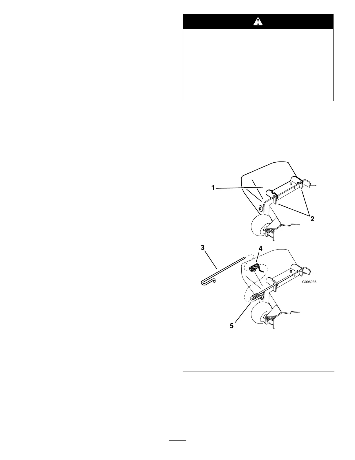
1.Disengagethespringfromthenotchinthedeector
bracketandslidetherodoutoftheweldeddeck
brackets,spring,anddischargedeector(Figure70).
Removethedamagedorworndischargedeector.
Figure70
1.Deectorassembly4.Spring
2.Deckbrackets
5.Springinstalledoverthe
rod
3.Rod
2.Positionthenewdischargedeectorassemblywith
thebracketendsbetweentheweldedbracketsonthe
deckasshowninFigure70.
3.Installthespringontothestraightendoftherod.
Positionthespringontherodasshowninsothe
shorterspringendiscomingfromundertherod
47