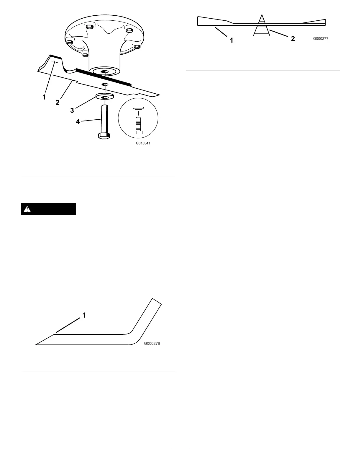
Figure55
1.SailAreaofBlade3.Curvedwasher
2.Blade4.BladeBolt
SharpeningtheBlades
WARNING
Whensharpeningblade,piecesofbladecouldbe
thrownandcauseseriousinjury.
Wearpropereyeprotectionwhensharpeningblade.
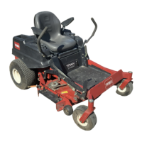
1.Usealetosharpenthecuttingedgeatbothendsof
theblade(Figure56).
Note:Maintaintheoriginalangle.Thebladeretains
itsbalanceifthesameamountofmaterialisremoved
frombothcuttingedges.
Figure56
1.Sharpenatoriginalangle
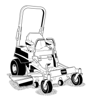
2.Checkthebalanceofthebladebyputtingitonablade
balancer(
Figure57).
Note:Ifthebladestaysinahorizontalposition,the
bladeisbalancedandcanbeused.Ifthebladeisnot
balanced,lesomemetalofftheendofthesailarea
only(Figure55).Repeatthisprocedureuntiltheblade
isbalanced.
Figure57
1.Blade2.Balancer
InstallingtheBlades
1.Installthebladeontothespindleshaft(Figure55).
Important:Thecurvedpartoftheblademustbe
pointingupwardtowardtheinsideofthemowerto
ensurepropercutting.
2.Installthespringdiskandbladebolt(rotatingit
clockwise).
Note:Thespringdiskconemustbeinstalledtoward
thebolthead(
Figure55).
3.Torquethebladeboltto135-150N-m(100-110ft-lb).
MowerDeckLeveling
Checktoensurethemowerdeckislevelanytimeyouinstall
themowerorwhenyouseeanunevencutonyourlawn.
Themowerdeckmustbecheckedforbentbladespriorto
leveling;anybentbladesmustberemovedandreplaced.
Refertothe,CheckingforBentBlades(page38),procedure
beforecontinuing.
Themowerdeckmustbeleveledside-to-siderstthenthe
fronttorearslopecanbeadjusted.
Requirements:
•Themachinemustbeonalevelsurface.
•Allfourtiresmustbeproperlyinated.RefertoChecking
theTirePressure(page35).
CheckingSide-to-SideLevel
Themowerbladesmustbelevelfromsidetoside.Checkthe
side-to-sidelevelanytimeyouinstallthemowerorwhenyou
seeanunevencutonyourlawn.
1.Parkthemachineonalevelsurfaceanddisengagethe
bladecontrolswitch.
2.Movethemotioncontrolleversoutwardtotheneutral
lockposition,stoptheengine,removethekey,setthe
parkingbrakeandwaitforallmovingpartstostop
beforeleavingtheoperatingposition.
3.Carefullyrotatethebladessidetoside.
4.Measurebetweentheoutsidecuttingedgesandtheat
surface(Figure58).
Note:Ifbothmeasurementsarenotwithin5mm
(3/16inch),anadjustmentisrequired;continuetothe
Levelingprocedure.
40