6
Assembly
Note:
Determine the left and right sides of the snowthrower by standing in the normal operating position.
Loose
Parts
DESCRIPTION QTY. USE
Carriage
bolts
Locknuts
Discharge chute
3
3
1
Installing the discharge chute
Plastic bushing
Capscrews
Locknuts
Chute crank and mounting bracket
1
2
2
1
Installing the chute crank (Models 38439,
38440, and 38445 only)
Installing
the Discharge Chute
Models 38413 and 38419 only
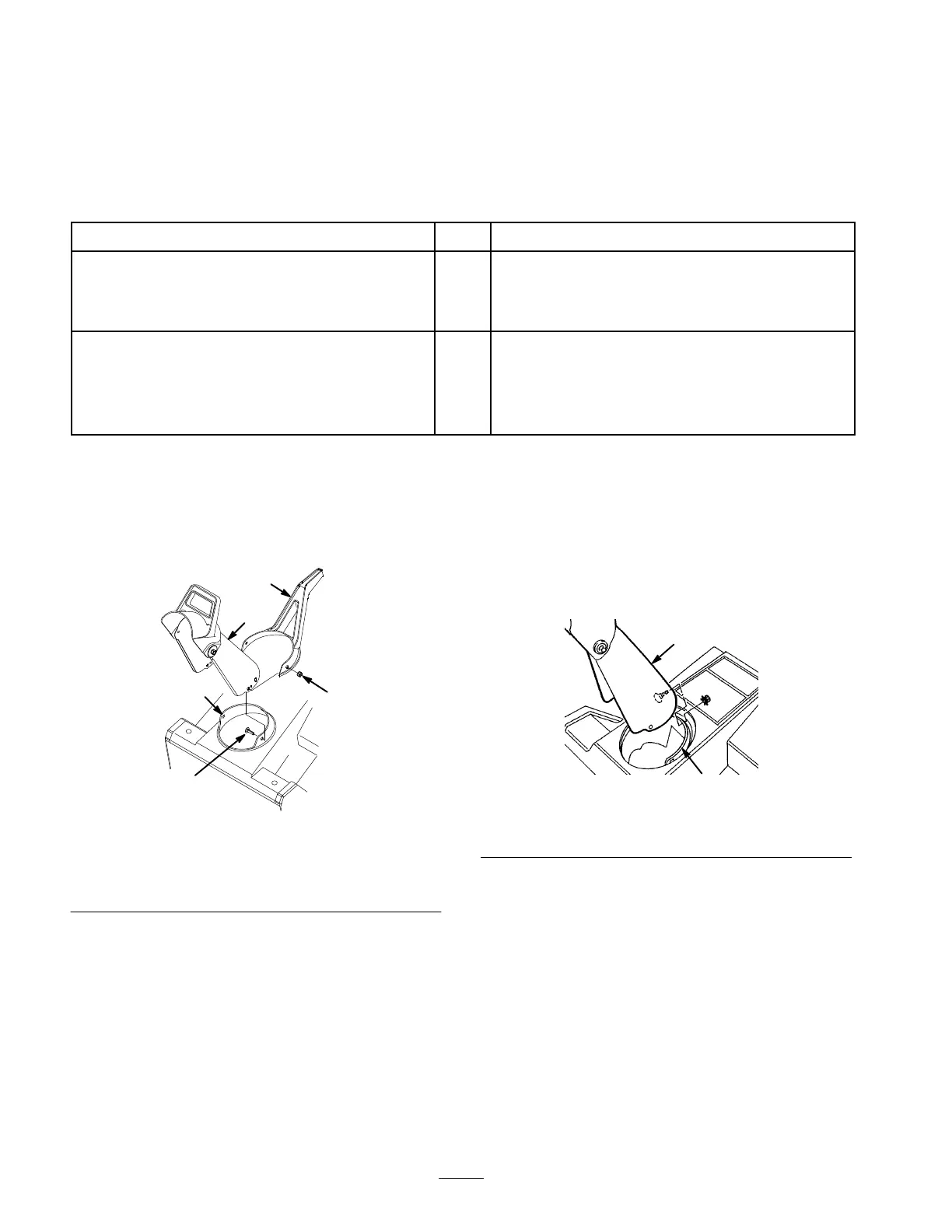
1. Place
the chute handle over the chute ring (Fig. 2).
m-3277
1
4
5
2
3
Figure
2
1. Chute
ring
2.
Discharge chute
3.
Chute handle
4.
Carriage bolt
5. Locknut
2. Insert
the dischar
ge chute between the chute ring and
the chute handle. (Fig. 2).
3.
Align the hole in the back of the chute with the center
hole in the ring.
Note:
Y
ou can rotate the chute ring for easier assembly
.
4.
Install a carriage bolt and a locknut through the center
holes, with the locknut on the outside.
5.
Install the carriage bolts and the locknuts through the
remaining holes, with the locknuts on the outside.
6. T
ighten all locknuts
securely.
Models 38439, 38440, and 38445 only
1. Set
the dischar
ge chute over the chute ring (Fig. 3).
1
2
636
Figure
3
1. Chute
ring
2.
Discharge chute
2. Align
the hole in the back of the chute with the center
hole in the ring (Fig. 3)
3.
Install a carriage bolt and a locknut through the center
holes, with the locknut on the outside (Fig. 3)
Note:
Y
ou can rotate the chute ring for easier assembly
.
4.
Install carriage bolts and locknuts through the
remaining holes, with the locknuts on the outside.
5. T
ighten all locknuts
securely.
 Loading...