Groundsmaster 4100--D/4110--DHydraulic System Page 4 -- 124
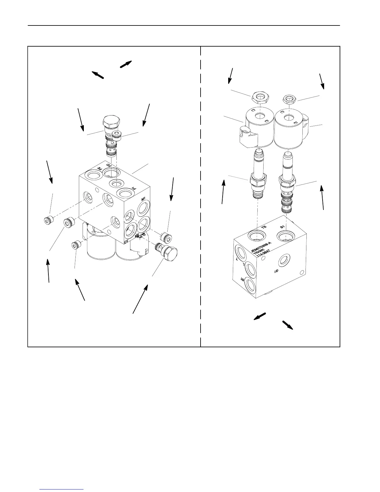
Fan Drive Manifold Service
1. Fan drive manifold
2. #4 zero leak plug with O--ring (3 used)
3. Check valve
4. #6 zero leak plug with O--ring (2 used)
5. Flow divider valve
6. Nut
7. Solenoid coil (2 used)
8. Proportional relief valve
9. Solenoid valve
10. Nut
Figure 87
FRONT
UP
B
1
2
3
4
5
2
2
4
7
9
8
6
10
7
20 ft--lb
(27 N--m)
20 ft--lb
(27 N--m)
20 ft--lb
(27 N--m)
50 ft--lb
(67 N--m)
25 ft--lb
(34 N--m)
25 ft--lb
(34 N--m)
25 ft--lb
(34 N--m)
25 ft--lb
(34 N--m)
25 ft--lb
(34 N--m)
5 ft--lb
(6.7 N--m)
5 ft--lb
(6.7 N--m)
FRONT
UP
NOTE: The ports on the manifold are marked for easy
identification of components. Example: P1 and P2 are
gearpumpc onnectionportsandS1isthesolenoidvalve
port (see Hydraulic Schematic in Chapter 10 -- Foldout
Drawings to identify the function of the hydraulic lines
and cartridge valves at each port).
NOTE: The fan drive manifold uses several zero leak
plugs. These plugs have a tapered sealing surface on
theplugheadthatisdesignedtoresistvibrationinduced
plugloosening.ThezeroleakplugsalsohaveanO--ring
as asecondary seal.Ifzero leak plug removal is neces-
sary, lightly rap the plug head using a punch and ham-
mer before using an allen wrench to remove the plug:
the impact will allow plug removal with less chance of
damage to the socket head of the plug.
 Loading...


