72
MAINTENANCE
3. Remove screw and replace the valve cone.
4. Inspect or replace two O-Ring's located on
Piston.
5. Replace the O-Ring's on the exterior of the
Housing.
6. Reassemble in opposite sequence.
7. Retest per inspection procedure.
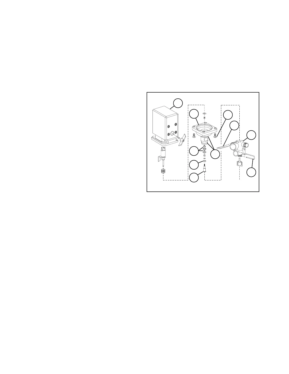
FIG. 8
1. Fork 6. O-Rings
2. Housing 7. Screw
3. Valve Cone 8. Housing ASM
4. Fork, Motor ASM 9. Motor Unit
5. Screw 10. O-Rings
FLOWMETER (SEE FIG. 7, page 71):
The Flowmeter may need to be disassembled for
periodic cleaning or to remove an obstruction.
Disconnect the signal wire and remove the
retaining cap by unscrewing it from the body. Pull
the Paddle Wheel assembly from the housing.
Once disassembled, use warm water and if
necessary, a mild detergent and soft bristled
brush to clean all parts. DO NOT USE
SOLVENTS OR DIESEL FUEL TO CLEAN THE
FLOWMETER. A magnet should work well for
removing fine metallic particles from the turbine.
Inspect all parts. Check for excessive bearing or
shaft wear. When assembling Flowmeter into
Housing, align Flowmeter Pin to hole on top of
Housing.
SPRAY PRO
MONITOR:
Store the monitor in a cool dry location if it will
not be used for an extended period of time, such
as during the off-season.
BOOM CONTROL VALVE:
IMPORTANT: Before performing any
maintenance, make sure electrical power to
the Boom Control Valve is shut off and this will
relieve line pressure.
Keep all electrical connections and motor
clean at all times.
A protective coating may be applied to the
completed electrical connections, if desired.
INSPECT VALVE CONE AND O-RING'S:
See parts drawing (FIG. 8) for reference.
1. Flush the sprayer with clean water and open
all Boom Control Valves. Shut sprayer engine
OFF.
2. Remove fork and remove hose for the Boom
Bypass valves. When the housing is drained
make sure everything is clear from the hose.
3. Start the sprayer. There should not be any
flow of liquid through the Boom Bypass passage.
If there is any leakage, the valve cone must be
changed. Shut sprayer engine OFF.
REPLACE VALVE CONE AND O-RING'S:
1. Disconnect 2-Pin electrical terminal.
2. Remove fork and pull the motor assembly off
the valve housing.
1
1795
3
4
5
7
6
10
9
2
8
 Loading...