77
FIG. 2
MAGNETIC HALL EFFECT SPEED AND
FLOW SENSORS:
Caution: Improper connection or voltage could
damage the Hall-effect sensor.
SPEED SENSOR:
Remove sensor from transaxle. Ground pin C
and connect clean 12 volts to pin A of the Speed
Sensor connector. Connect the positive lead
(red) of an ohmmeter or continuity tester to pin
B, and the negative lead (black) of the ohmmeter
or continuity tester to pin C, of the Speed Sensor
connector.
Holding the tip for sensor in open air should
result in a very high resistance (infinite), while
holding the tip of the sensor to within 1/16" of
steel material should result in a very low resistance
(near zero).
SPEED INPUT:
Turn rotary dial to SPEED position and
disconnect speed sensor from the main harness.
Using a clip lead or other jumper wire (such as a
paper clip bent in a U), several times rapidly
short together pins B and C of the 3-pin
connector (See FIG. 2). The monitor should
respond with some speed reading.
FLOWMETER:
The Flowmeter has an indicating light on the top
for diagnostics. As fluid flows through the meter,
or if the Rotor is spun by hand, the light should
flash with a frequency proportional to the speed
of the Rotor. No light at all indicates no power to
the meter. A steady light indicates a faulty meter.
FLOW INPUT:
Turn rotary dial to TOTAL VOLUME (not APP.
RATE), turn Master ON/OFF Switch to ON, and
turn all Boom sections ON. Disconnect flow
sensor from the main harness. Using a clip lead
or other jumper wire (paper clip bent in a U),
several times rapidly short together pins B and C
of the 3-pin connector. (See FIG. 2) The monitor
should respond with some flow reading.
1. Pin A- 12V Pos. 2. Pin B- Signal
3. Pin C- 12V Neg.
SPEED SENSOR AND FLOWMETER POWER:
The Speed Sensor and Flowmeter both have a
12 volt power supply. Check for 12 volts between
pins A and C in the connector at the sensors. If
power is not present, make sure the sensor power
wire is not open or shorted to ground or to
another wire. If this wire has a problem, the
monitor may exhibit erratic behavior or not
function at all.
SPRAY PRO
- TROUBLESHOOTING
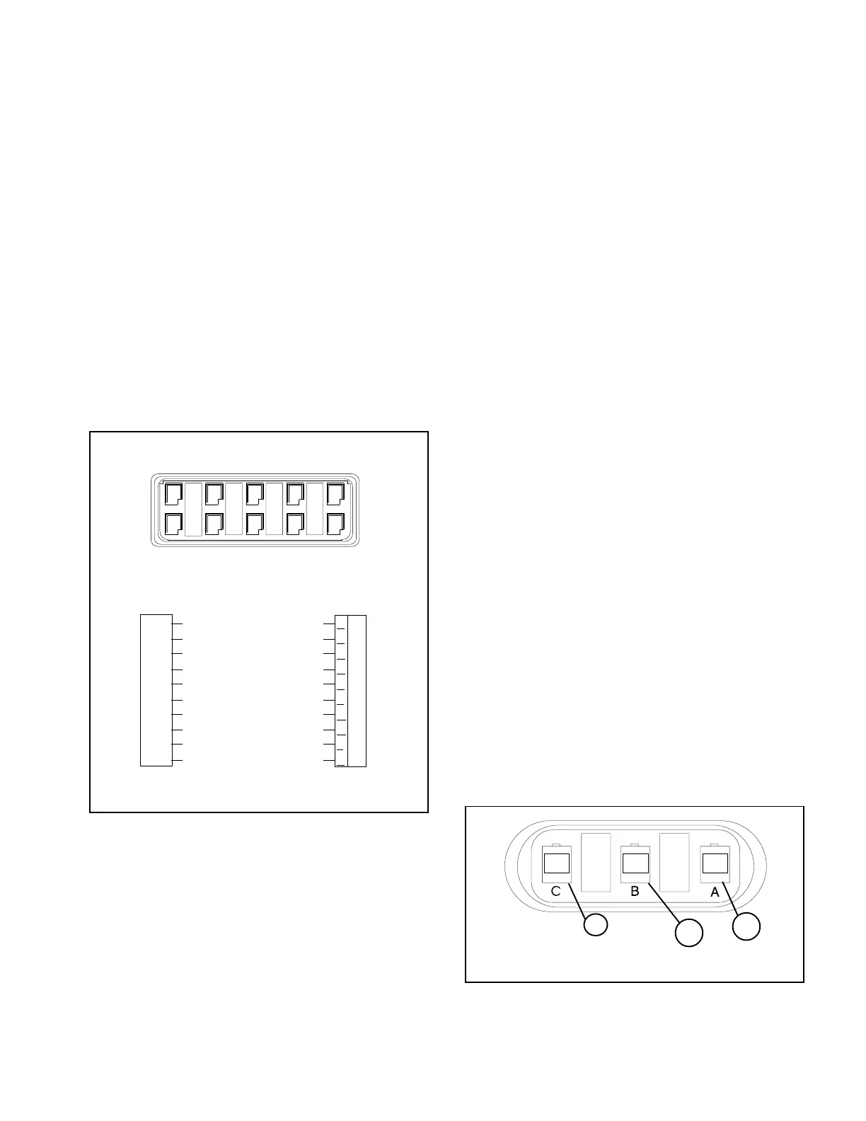
FIG. 1
1. Pinout Locations
1797-1250
CHECKING INDIVIDUAL COMPONENTS:
MONITOR:
The only way to field test a monitor is to connect
it to a harness on a vehicle with a known working
console.
HARNESS:
The harness can be checked using an ohmmeter
or continuity tester. The wiring diagram below
(See FIG. 1) shows the pin out of all connectors.
Simply check for continuity between connected
pins and for no continuity between unconnected
pins.
POWER:
The Spray Pro cable has a ten-pin connector
labeled A-K. (See FIG. 1) Check between J-K
with a voltmeter or test light. If there is no power,
trace cable toward battery looking for breaks. Also
check fuses that supply power to the monitor.
1798
1
2
3
3-Pin Connector
A
B
C
D
E
F
G
H
J
K
E
D
CBA
F
GHJK
Monitor
Connection
Run/Hold Signal - Brown
Option Control - Red
Speed Power - Orange
Speed Signal - Yellow
Speed Ground - Green
Flow Power - Blue
Flow Signal - Violet
Flow Ground - Gray
Battery Ground - White
Battery Power - Black
SPRAY PRO
™
Monitor
10-Pin Metri-Pack Tower
Main Wiring Harness Ten Pin Connector
 Loading...