Do you have a question about the Toro Reelmaster 2000-D and is the answer not in the manual?
Space to record the machine's model and serial numbers for service.
Explains the meaning of Danger, Warning, Caution, Important, and Note signal words.
Machine meets or exceeds specific CEN, ISO, and ANSI safety standards.
General safety instructions for operating the machine safely.
Emphasizes operator training, familiarity with controls, and owner responsibility for safe use.
Recommends wearing footwear, trousers, hard hat, glasses, and ear protection while mowing.
Thoroughly inspect the area and remove objects that could be thrown by the machine.
Safe practices for storing and refueling, emphasizing flammability.
Check operator presence controls, safety switches, and shields for proper function.
Avoid operating the engine in confined spaces due to carbon monoxide.
Mow only in daylight or good artificial light.
Engage parking brake, disengage clutches, shift to neutral before starting.
Caution on slopes, avoiding sudden stops/starts, maintaining low speed and gear.
Stay alert for humps, hollows, holes, and other terrain hazards.
Use care when pulling loads, near traffic, or crossing roadways.
Do not direct discharge toward bystanders; ensure guards and shields are in place.
Do not change governor settings or overspeed the engine to avoid injury.
Stop on level ground, disengage power, set brake, stop engine, remove key.
Reduce throttle during run-out and turn off fuel at conclusion of mowing.
Keep hands and feet away from cutting units; look behind before backing.
Slow down and use caution when turning and crossing roads; stop reels if not mowing.
Do not operate the mower under the influence of alcohol or drugs.
Use care when loading or unloading the machine into a trailer or truck.
Use care when approaching blind corners or objects that obscure vision.
Carefully release pressure from components with stored energy.
Disconnect battery (negative first) and remove spark plug wire before repairs.
Use care and gloves when checking cylinders/reels.
Keep hands/feet away from moving parts; avoid adjustments with engine running.
Charge batteries in a well-ventilated area away from sparks and flames.
Product can amputate hands/feet and throw objects; follow all safety instructions.
Using the product for non-intended purposes is dangerous.
Engine exhaust contains deadly carbon monoxide; do not run indoors.
Know how to stop the engine quickly.
Do not operate wearing tennis shoes; safety shoes and long pants are advisable.
Handle fuel carefully and wipe up spills.
Check interlock switches daily; replace all switches every two years.
Sit on the seat before starting; pay attention to prevent loss of control.
Avoid driving near sand traps, ditches; reduce speed on turns; watch for holes.
Apply service brakes when going downhill for control.
Ensure grass baskets are in place; raise cutting units for transport.
Do not touch the engine, muffler, or exhaust pipe while hot.
If stalling on a slope, back down slowly; do not turn around.
Stop mowing if people/pets appear; resume only when area is clear.
Have an Authorized Toro Distributor check maximum engine speed (3200 RPM).
Contact Authorized Distributor for repairs; use only Toro-approved attachments.
Unit has a guaranteed sound power level of 105 dBA/1 pW per Directive 2000/14/EC.
Equivalent continuous A-weighted sound pressure level at operator ear is 87 dBA per Directive 98/37/EC.
Unit does not exceed 2.50 m/s² at hands per ISO 5349.
Unit does not exceed 0.50 m/s² at posterior per ISO 2631.
Decals are visible and near danger areas; replace damaged or lost decals.
Decals related to locking and unlocking the parking brake.
Decals for slow/fast reel speed and reel height adjustments.
Warning to operate only when all shields are securely fastened.
Battery contains lead; do not dispose of in garbage.
Read operator's manual before performing any maintenance.
Warning about crushing of fingers or hands; stay a safe distance away.
Hazard from moving parts; stay away from them.
Keep bystanders a safe distance from the machine due to thrown objects.
Hazard from moving parts; stay away from them.
Warning about tipping on slopes greater than 15 degrees.
Lock parking brake, stop engine, and remove key before leaving the machine.
Explosion hazard; wear eye protection.
Caustic liquid hazard; flush skin with water.
Fire hazard; sparks, flame, and smoking prohibited.
Poison hazard; keep children away from the battery.
Warning: do not touch hot surfaces.
Warning: read the operator's manual.
Check engine oil level.
Engine oil drain procedure using a 17mm socket.
Check hydraulic oil level at the bottom of the sight glass.
Check fan/water pump and hydraulic pump belts.
Fill coolant level to the middle of the horizontal neck.
Fuel type is Diesel only.
Lubricate grease points every 50 hours.
Lubricate grease points every 8 hours.
Clean radiator screen.
Service the air cleaner.
Check water separator/fuel filter.
Check the battery.
Tire pressure 16-20 psi.
Check fuses.
Details fluid types, capacities, and change intervals for engine oil, hydraulic oil, etc.
Steps for starting the engine: sit, engage brake, turn off reels, turn key to ON/START.
Steps for stopping the engine: turn key to OFF, remove key, engage brake.
Caution against using starting fluid.
Warning to read and understand the operator's manual before operating.
Lever to control engine speed (FAST/SLOW).
Controls engine start, run, and stop functions.
Lever to raise and lower cutting units.
Controls for raising, lowering, and locking cutting units.
Switch to engage and disengage the cutting unit drive.
Indicates engine states: run, start, stop.
Controls for fast and slow engine speeds.
Pedal moves machine forward/backward and stops it.
Reverse pedal stop set at factory for 3 MPH max reverse speed.
Switch for starting, stopping, and preheating engine.
Lever to increase or decrease engine speed.
Lever to raise and lower cutting units.
Locks cutting units in raised position for transport.
Switch to engage/disengage cutting units.
Indicates total machine operating hours.
Light indicates low engine oil pressure.
Light and automatic shutdown for high coolant temperature.
Indicator light for glow plug operation.
Light indicates reels are lowered to cutting position.
Engage parking brake by pulling lever back to prevent movement.
Knob to adjust reel speed for desired clip rate.
Knob to select backlapping or mowing mode.
Adjust seat fore and aft for operator comfort.
Details configuration, engine, radiator, electrical, fuel capacity, and drive.
Specifies ground speed ranges and tire specifications.
Describes frame construction, steering mechanism, and brake system.
Lists hand-operated controls and dashboard gauges/warning lights.
Details seat adjustment and hydraulic cutting unit lift system.
Provides wheel tread width, wheel base, width, transport width, and length.
Lists height without seat and various weight configurations.
Lists 3-Wheel Drive Kit, Weight Kit, and Rear Weight Kit with model numbers.
Lists 27" and 32" Lift Arm Kits, and various Blade Cutting Units.
Lists Basket Kit with model number.
Lists all parts required for assembly and their uses.
Instructions for applying European compliance decals to specific locations.
Steps to mount the wheel assembly and tighten lug nuts.
Procedure to adjust carrier frame height using lift arms and pivot rod.
Steps to position and mount carrier frames onto cutting units.
Securing mounting links to carrier frames with capscrews and locknuts.
Procedure to install pivot rods, lift arms, and counterbalance arms.
Securing lift chains to lift cylinder pins and lift arm tabs.
Position cutting units, remove covers, install O-ring and gasket.
Mount motor and spider coupling to cutting unit drive end.
Slide thrust washer onto lift arm pivot rod and cutting unit carrier frame.
Secure carrier frame to pivot rod with washer and capscrew.
Secure tipper chains to carrier frames of 27" and 32" cutting units.
Grease all lift arm and carrier frame pivot points.
Warning about the heavy load of tensioning springs.
Springs balance cutting units and transfer weight for traction.
Recommended settings for counterbalance springs based on reel type.
Hooking springs into lift tabs for 27" cutting units.
Explains how spring tension affects weight distribution and traction.
Securing spring to counterbalance arms with shackle, clevis pin, and cotter pin.
Install vinyl cover over rear counterbalance spring before installation.
Mounting spring anchors to lift tabs for 32" cutting units.
Hooking springs into spring anchors and counterbalance arms for 32" units.
Procedure to tension springs by moving shackle on counterbalance arm.
Chart to determine weight kits required based on cutting unit configuration.
Note on filling tires with calcium chloride for ballast.
Details on calcium chloride types and solution preparation for tire ballast.
Warning about lead in battery posts and terminals.
Filling battery cells with electrolyte.
Danger warning about sulfuric acid in electrolyte.
Connect charger and charge battery at specified rate and duration.
Warning about explosive gases produced during charging.
Adjust electrolyte level to fill ring after charging.
Warning about incorrect battery cable routing and spark hazards.
Connecting positive (red) and negative (black) battery cables correctly.
Procedure for cleaning and coating terminals if corrosion occurs.
Caution about leaving key in switch to prevent accidental starting.
Procedure to check engine oil level on a level surface.
Details API classification and preferred/alternate oil types.
Note on allowing proper venting when adding oil to prevent overflow.
Requirement for clearance between fill device and valve cover for venting.
Importance of keeping oil level between upper and lower limits to prevent engine failure.
Engine runs on No. 2 diesel fuel; tank capacity is 6.5 gallons.
Danger warning about flammability and explosiveness of diesel fuel.
Fill tank outdoors, use funnel, do not overfill (leave 1 inch space).
Never smoke when handling fuel; stay away from open flames or sparks.
Store fuel in a clean, safety-approved container with cap in place.
System uses 50/50 water/glycol mix; check level daily.
Clean radiator screen, radiator, and oil cooler daily or hourly if dusty.
Caution that hot coolant escapes when opening cap; use rag and open slowly.
Check radiator fill level and surge tank level.
Replenish coolant if low, but do not overfill.
Reservoir capacity and recommended Toro fluid.
Requirements for alternate fluids (ISO VG 46) and caution on substitutions.
Red dye additive available for spotting leaks.
Information on Toro Biodegradable Hydraulic Fluid and alternate Mobil EAL 224H.
Note on fluid compatibility when changing types.
Check fluid level in sight gauge (cold vs. hot).
Procedure to fill reservoir if fluid level is low, do not overfill.
Prevent system contamination by cleaning containers and tools.
Tires are over-inflated for shipping; correct pressure is 16-20 psi.
Maintain recommended pressure for quality-of-cut and performance.
Check for light contact across the full length of reel and bedknife daily.
Failure to maintain proper torque can cause personal injury.
Torque nuts to 45-65 ft.-lb. after 1-4 hrs, 10 hrs, and every 200 hrs.
Close fuel shut-off valve when storing the machine.
Fuel system may need bleeding after new engine, fuel loss, or maintenance.
Steps to start the engine: parking brake, neutral pedal, throttle, key positions.
Caution to avoid overheating starter motor by limiting cranking time.
Steps to stop engine: idle throttle, disengage reels, turn key to OFF.
Danger warning about flammability and explosiveness of diesel fuel.
Unlatch and raise the hood to access fuel system components.
Loosen air bleed screw on top of fuel filter/water separator.
Tighten air bleed screw after bleeding procedure.
Engine should start after bleeding; refer to injector bleeding if needed.
Caution against tampering with interlock switches; replace damaged ones.
Step-by-step checks of interlock functions with operator on/off seat.
Towing recommended only for short distances in emergencies.
Do not tow faster than 2-3 MPH to avoid drive system damage.
Locating and rotating the bypass valve to tow the unit.
Machine produces sound > 85 dBA; wear hearing protection.
Practice operating to become familiar with hydrostatic transmission.
Regulate traction pedal and engine speed for power.
Use speed selector for constant speed; avoid on hilly terrain.
Guidelines for traversing slopes (up/down, not side-to-side) and avoiding steep slopes.
Plan ahead, avoid sudden stops/turns, use reverse pedal for braking.
Match reel speed to height of cut for consistent quality.
Verify height-of-cut setting on cutting units.
Turn reel speed control knob to the number setting from the chart.
Adjust reel speed one position +/- to fine-tune cut quality.
Chart showing recommended reel speeds for 5-blade reels by height of cut.
Chart showing recommended reel speeds for 8-blade reels by height of cut.
Notes on recommended height-of-cut and mowing speeds for specific reels.
Practice starting, stopping, raising/lowering units, and turning.
Inspect area for debris and clear if necessary.
Mow in an alternate pattern to prevent grass laying down.
Ensure cutting units are in the fully up position for transport.
Reduce speed and use caution on slopes and uneven terrain.
Watch for and avoid holes, drop-offs, and other hidden hazards.
Wash machine with a garden hose without a nozzle.
Keep radiator screen, radiator, and oil cooler free of dirt.
Inspect for hydraulic fluid leaks, damage, wear, and check cutting units.
Electronic device monitoring and controlling electrical features for safety.
Module monitors inputs (neutral, brake, PTO, etc.) and energizes outputs (PTO, Starter, ETR).
Green LEDs identify inputs and output status.
Output circuits are energized by specific input conditions.
SCM does not connect to external computer; cannot be reprogrammed.
Decal on SCM includes symbols; chart identifies symbols.
Logical steps for troubleshooting SCM faults using input/output LEDs.
Chart detailing input/output requirements for specific product functions.
Steps for troubleshooting by checking input LEDs, output LEDs, and voltage.
Check belts, change oil filter, torque wheel nuts.
Change engine oil/filter, check engine RPM.
Inspect air filter, lubricate fittings, check belts.
Check engine and traction belt tension.
Change engine oil and filter.
Service air filter, replace fuel/hydraulic filters.
Replace hydraulic fluid, check battery, check traction linkage.
Replace hoses, flush cooling system, drain fuel/hydraulic tanks.
Refer to engine manual for additional maintenance procedures.
List of checks for safety interlocks, brakes, engine oil, cooling system, etc.
Section for recording inspection details and areas of concern.
Summary of checks and services with corresponding numbers.
Details fluid types, capacities, and change intervals for engine oil, hydraulic oil, etc.
Caution regarding ignition switch and spark plug wire before maintenance.
Lubricate regularly with No. 2 grease; daily if dusty/dirty conditions.
Lists specific traction unit bearings and bushings requiring lubrication.
Apply grease to slots in cylinder support.
Check air cleaner body and intake system for leaks or damage.
Service filter every 200 hours or earlier if performance suffers.
Ensure cover is seated correctly and seals with the body.
Release latches to remove the air cleaner cover.
Use low-pressure air to remove debris from primary filter.
Remove and replace the primary filter; cleaning used elements not recommended.
Clean dirt ejection port and outlet valve in the cover.
Orient rubber outlet valve downward between 5:00 to 7:00.
Remove the radiator screen.
Spray radiator with hose or blow with compressed air from fan side.
Thoroughly clean the oil cooler and surrounding components.
Change oil/filter after first 50 hours, then every 150 hours.
Park on level surface, lower units, set brake, turn engine off, remove drain plug.
Apply oil to new filter seal, screw on until gasket contacts plate, tighten 1/2-2/3 turn.
Change hydraulic filter initially after five hours, then every 200 hours or yearly.
Change hydraulic fluid every 400 hours or yearly.
Clean around filter, remove filter, apply oil to new filter gasket, tighten.
Fill reservoir to proper level after filter change.
Start engine at low RPM to purge air from the system.
Test ports used for pressure testing traction and reel circuits.
Check fuel lines and connections every 400 hours or yearly.
Drain separator daily; replace canister every 400 hours.
Clean area around filter canister mounting surface.
Lubricate gasket, install canister, rotate to tighten.
Use only if fuel system purged and engine still won't start.
Loosen pipe connection to nozzle and holder assembly.
Watch fuel flow around connector while starting engine.
Tighten pipe connector securely after observing solid flow.
Adjust traction cam if machine moves when pedal is in neutral.
Warning about machine falling if not supported adequately.
Loosen locknut on traction adjustment cam.
Rotate cam hex to determine mid-position of neutral span.
Tighten locknut securing the adjustment.
Warning about personal injury from hot or moving parts during adjustment.
Remove support blocks, lower machine, test drive for neutral operation.
Check and adjust neutral switch operation after pump plate adjustment.
Adjust switch if circuit is made when in neutral and broken with 1 inch pedal travel.
Loosen locknut securing the switch adjusting screw.
Tighten the locknut after adjusting switch location.
Ensure belts are properly tensioned for operation and wear prevention.
Check and adjust hydraulic pump belt tension.
Tighten belt to eliminate slippage but do not overtighten.
Check alternator belt tension by measuring deflection.
Adjust alternator belt tension by rotating alternator.
Specifications for new and used belt deflection under force.
Adjust linkage if pedal contacts footrest or max speed is unattainable.
Remove right-hand panel to expose the traction rod.
Remove right-hand panel to expose the traction pedal damper.
Loosen locknut securing the damper pivot.
Depress traction pedal fully forward to access damper.
Compress damper, allow extension, tighten locknut.
Damper must contact reverse stop when pedal is fully depressed rearward.
Check neutral switch adjustment after damper adjustment.
Remove both front wheels before adjusting hand brake.
Ensure the brake is in the OFF position.
Adjust clevis to decrease distance between brake levers.
Operate vehicle at low speed to check brake engagement on both wheels.
Maintain electrolyte level and keep battery top clean.
High temperatures cause faster battery rundown.
Check electrolyte level every 25 operating hours or 30 days in storage.
Maintain cell level with distilled water, do not overfill.
Install filler caps with vents pointing to the rear (toward fuel tank).
Danger warning about sulfuric acid in electrolyte.
Clean battery top periodically with ammonia/bicarbonate solution.
Battery cables must be tight for good electrical contact.
California Proposition 65 warning about lead in battery posts.
Incorrect routing can cause sparks, damage, and explosion.
Always disconnect negative first, connect positive first.
Procedure for cleaning and coating terminals if corrosion occurs.
Remove and charge fully if stored over 30 days; store in a cool atmosphere.
Specific gravity of a fully charged battery is 1.265 - 1.299.
Fuses are located on the back of the instrument panel.
Danger warning about hand/foot injury or death from moving reels.
Caution about personal injury from contact with reels or moving parts.
Do not place hands/feet in reel area, do not adjust reels while engine runs.
Position machine, lower units, stop engine, engage brake, remove key.
Rotate backlap knob to backlap position; rotate reel speed knob to position 1.
Do not rotate backlap knob from mow to backlap while engine is running.
Turn reels OFF to adjust cutting units; turn engine OFF.
Stop engine, rotate backlap knob to MOW, set reel speeds, wash compound.
Run file across bedknife front face after lapping to remove burrs.
Diagram showing electrical components and their connections.
Identifies fuse ratings and locations.
Diagram showing hydraulic system components and fluid flow.
Identifies pumps, motors, valves, and reservoir.
Explains warranty on evaporative emission control system for 2006 model year equipment.
System warranted for two years; defective parts repaired or replaced.
Owner responsible for required maintenance and presenting equipment for service.
Details warranty period start, general coverage, and part warranty interpretation.
Lists parts covered under the evaporative emission warranty.
Two-year or 1500-hour limited warranty for defects in materials or workmanship.
Procedure for notifying distributor/dealer and contacting Toro for service.
Owner responsible for required maintenance; failure can void warranty.
Lists exclusions like non-Toro parts, abuse, neglect, normal wear and tear.
Repair by Authorized Dealer is sole remedy; limits on incidental/consequential damages.
Notes that Emissions Control System Warranty may be separate and not subject to hour limits.
Advice for customers outside the US/Canada to contact their local distributor.
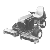
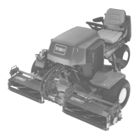
| Brand | Toro |
|---|---|
| Model | Reelmaster 2000-D |
| Category | Lawn Mower |
| Language | English |