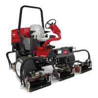
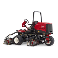
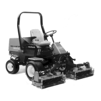
Reelmaster 3550-- D Page 5 -- 21 Electrical System
Light Switch
The light switch is located on the control panel (Fig. 24).
This rocker switch allows th e headlights to be turned on
and off.
Testing
1. Park machine on level surface, lower cutting units,
stop engine, apply parking brake and remove key from
ignition switch.
2. Remove cover from control panel to g ain access to
light switch.
3. Disconnect wire harness electrical connector from
the light switch.
4. With the use of a multimeter (ohms setting), the light
switch functions may be tested to determine whether
continuity exists between the various terminals for each
position. The switch terminals are marked as shown in
Figure 25. The circuitry of the light switch is shown in the
chart below. Verify continuity between switch terminals.
SWITCH
POSITION
NORMAL
CIRCUITS
OTHER
CIRCUITS
ON 2+3 5+6
OFF 2+1 5+4
5. Replace light switch if testing identifies that switch is
faulty.
6. After testing is completed, connect the wire harness
connector to the light switch. Install control panel cover.
1. Control panel 2. Light switch
Figure 24
2
1
Figure 25
BACK OF SWITCH
NOTE: Light switch terminals 1, 4, 5 and 6 are not used
on Reelmaster 3550 machines.

 Loading...


