.
.
G015323
----...3
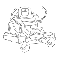
Figure 53
1. Hanger bracket 4. Side locking nut
2. Slotted adjustment 5. Side carriage bolt
position
3. Fixed position
Loosen the rear locking nut on the hanger bracket
just enough to move the bracket (Figure 54).
a.,
4_
Figure 54
G015324
1. Hanger bracket 3. Side locking nut
2. Rear locking nut 4. Adjustment notches
Use the notches on the welded bracket to measure
the amount of adjustment. Each notch surface is
equivalent to 0.25 inch, while a single side is 0.125
inch (Figure 55). Adjust the height of the mower
deck to the desired height.
1,
Figure 55
0.25 inch 2. 0.125 inch
iO.
11.
Stop the deck at the adjusted position and tighten the
rear locldng nut on the hanger bracket to hold the
new position (Figure 54). Tighten the side locking
nut on the hanger bracket.
Continue leveling the deck by checking the
front-to-rear blade slope; refer to Adjusting the
Front-to-Rear Blade Slope.
Adjusting the Front-to-Rear Blade
Slope
Check the front-to-rear blade level any time you install
the mower. If the front of the mower is more than
5/16 inch (7.9 ram) lower than the rear of the mower,
adjust the blade level using the following instructions:
1. Park the machine on a level surface and disengage
the blade control switch.
. Move the motion control levers outward to the
park position, stop the engine, remove the ke), and
wait for all moving parts to stop before leaving the
operating position.
3. Set the height-of-cut lever to middle position.
.
Note: Check and adjust the side-to-side blade
level if you have not checked the setting; refer to
Side-to-Side Leveling.
Carefully rotate the blades so they are facing front to
rear (Figure 56 and Figure 57).
41
 Loading...