EasyManuals Logo

Toro TWRS User Manual

Toro TWRS
28 pages
To Next Page IconTo Next Page
To Previous Page IconTo Previous Page
Page #9 background imageLoading...
Page #9 background image
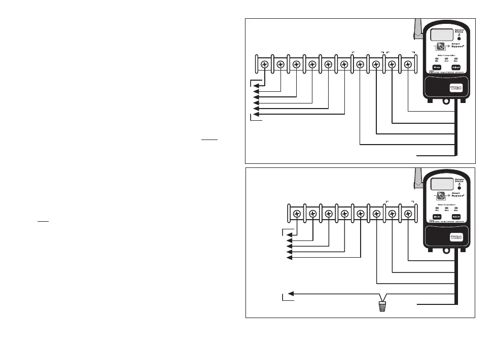
For a normally-open sensor, attach the
Yellow wire to the remaining sensor terminal.
Tape back the Brown wire. See Figure 3.
4. Attach the Red wires to the 24 Vac terminals.
Important Most controllers with sensor
connections also provide a control switch to
bypass sensor operation if necessary. Check
the switch setting to make sure it is not in
the Bypass or Active position.
Wiring Procedure II (no sensor feature)
1. Locate the valve common wire terminal,
generally labeled “C” or “COM”, and remove
all
common wires for valves, pump relay, etc.
2. Attach the White wire to this terminal.
3. Splice the Brown wire to the common wires
and insulate the connection using a wire nut
or electrical tape. Tape back the Yellow wire.
See Figure 4.
4. Attach the Red wires to the 24 Vac terminals.
7
COM
PUMP/
MV
24 VAC
21
34
SENSOR
Red
Red
Red
White
Yellow
Red
White
Yellow
Brown
X
To Valves
PUMP/
MV
24 VAC
COM
21
34
Red
Red
Red
White
White
Brown
Red
Common
To Valves and
Pump/MV
Yellow
X
Figure 3 - Normally-open Sensor
Figure 4 - Splice Valve Common
RainSensorAlpha7 3/10/2005 3:31 PM Page 7

Questions and Answers:

Question and Answer IconNeed help?

Do you have a question about the Toro TWRS and is the answer not in the manual?

Toro TWRS Specifications

General IconGeneral
BrandToro
ModelTWRS
CategoryIrrigation System
LanguageEnglish

Related product manuals