14
-EN
Air Conditioning Control System (Touch Screen Controller) Installation Manual
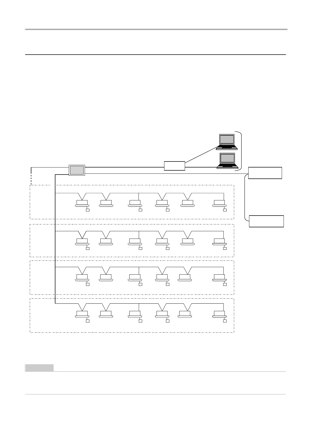
Wiring connections
This section shows wiring connection examples with the indoor units, power meter interface, digital I/O interface, and remote
monitoring PC.
Air conditioning unit group settings
• Indoor units can be set together for each group unit.
• There is a TCC-LINK 1 and a TCC-LINK 2 for each TCC-LINK communication line. There are 64 groups in each line, and
there are 128 groups and 128 zones for TCC-LINK 1 and TCC-LINK 2 together.
Interface connection
Connect the power meter interface and the digital I/O interface to the RS-485 cable line. For details of the connection method
refer to the interface installation manual.
Set the termination resistance of TCC-LINK 1 and 2 at the air conditioner.
When you remove the rear panel of this Unit, there is SW100 which is the termination resistance of TCC-LINK 1 and 2.
In both cases, please use in the "Open": OFF state.
Gr1 Gr5 Gr8 Gr16
Gr32Gr32
Gr32Gr48
Gr2 Gr10
Gr17
Gr33 Gr35
Gr22 Gr25
Gr39 Gr43
Gr30
Gr45
Gr32Gr64Gr49 Gr50 Gr55 Gr58 Gr60
Gr19
TCC-LINK1
TCC-LINK2
Group
1 to 16
Group
17 to 32
Group
33 to 48
Group
49 to 64
Gr = Group
Hub
LAN cable
LAN cable
RS-485
Power meter
interface
Digital I/O
interface
Remote monitoring PC
 Loading...