EN-20EN-19
10
EN
Airtight test/Air purge, etc.
For airtight test, air purge, addition of refrigerant, and gas leak check, follow the Installation Manual attached to
the outdoor unit.
REQUIREMENT
Be sure to use the tool such as charge hose exclusive to R410A.
Do not turn on the power until the airtight test and the vacuuming have fi nished.
(If turning on the power, the incorporated PMV is closed fully and the period until the vacuuming fi nishes
elongates.)
Open fully valves of the outdoor unit
Gas leak check
Check with a leak detector or soap water whether gas leaks or not, from the pipe connecting section.
REQUIREMENT
Use a leak detector manufactured exclusively for HFC refrigerant (R410A, R134a, etc.).
Heat insulating process
Perform heat insulating for each pipes
separately.
In cooling time, temperature at both liquid
and gas sides becomes lower.
Therefore, perform heat insulating process
suffi ciently to avoid dewing.
• For heat insulator of pipe at gas side, be
sure to use one with heat-resisting temp.
248 °F (120 °C) or more.
• Using the attached heat insulating pipe,
perform heat insulating process securely
for pipe connecting part of the Flow
Selector units without clearance.
The slit shall be
upper side.
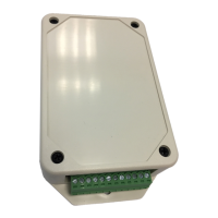
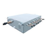
Flow Selector unit
Heat insulating
pipe (Attached)
Heat insulator
• Indoor unit side
• Outdoor unit side
Heat insulating pipe
(Accessory)
Heat insulating pipe
(Accessory)
(Stopper-pipe)
Heat insulating pipe
(locally procured)
Binding band
(Accessory)
[Port with the pipe connected.]
Binding band
(Accessory)
[Side with the pipe connected.]
Binding band
(Accessory)
[Port without the pipe.]
Binding band
(Accessory)
[Side without the pipe connected.]
Heat insulating pipe
(Accessory)
Heat insulating pipe
(locally procured)
Heat insulating pipe
(locally procured)
(Stopper-pipe)
Heat insulating pipe
(Accessory)
REQUIREMENT
Apply the heat insulation to the pipe connecting section of the Flow Selector unit securely up to the root without
exposure of the pipe. (The pipe exposed to the outside causes water leak.)
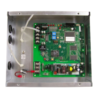
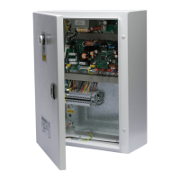
7 ELECTRICAL CONNECTION
CAUTION
• Consult local building codes, NEC (National Electrical Code) or CEC (Canadian Electrical Code) for special
requirements.
• If incorrect / incomplete wiring is carried out, it will cause an electrical fi re or smoke.
• Install circuit breaker is not tripped by shock waves. If circuit breaker is not installed, an electric shock may be
caused.
• Use the cord clamps attached to the product.
• Do not damage or scratch the conductive core and inner insulator of power and communication wires when
peeling them.
• Use the power cord and communication wire of specifi ed thickness, type, and protective devices required.
• Do not connect 208 / 230 V power to the terminal blocks (A, B) for communication wiring. (Otherwise, the system
will fail.)
• Perform the electric wiring so that it does not come to contact with the high-temperature part of the pipe. The
coating may melt resulting in an accident.
REQUIREMENT
• For power supply wiring, strictly conform to the Local Regulation in each country.
• After connecting wires to the terminal blocks, provide a trap and fi x wires with the cord clamp.
• Run the refrigerant piping line and communication wiring line in the same line.
• Do not turn on the power of the Flow Selector unit until vacuuming of the refrigerant pipes completes.
• This Flow Selector unit has multiple ports. So piping and wiring to the same indoor unit shall be connected to the
same number (1, 2, 3, 4
…
) of port.
Power supply wire and communication wires specifi cations
Power supply wire and communication wires are locally procured.
For the power supply specifi cations, follow to the table below. If capacity is little, it is dangerous because overheat
or burnout may be caused.
Power supply
• Power supply wire specifi cation: Cable 3-core AWG12.
Power supply 208 / 230 V-1-60 Hz
Power supply switch / circuit breaker or power supply wiring / fuse rating for Flow Selector units should be selected by the
accumulated total current values of the Flow Selector units.
Power supply wiring Below 164' (50m) AWG12
Communication wiring
• 2-core with non-polarity wire is used for wiring of the communication wiring.
• Wire size : AWG14 to 20
• Up to 656' (200m) total length of wiring between indoor units and Flow selector unit. (L2 + L3)
• Up to 984' (300m) (L1 + L2 + L3)
• Up to 984' (300m) (L1)
NOTE
• Use copper supply wire.
• Use UL wire rated 600 V for the power supply.
• Use UL wire rated 300 V for the remote control wires and control wires.
01_1118431101-EN.indd 1001_1118431101-EN.indd 10 7/12/2559 BE 9:53 AM7/12/2559 BE 9:53 AM
 Loading...