EN-16EN-15
8
EN
Heat insulating process
• Using the attached drain hose heat insulator, lap the connecting section and the drain hose without clearance,
and then tighten with two handing band so that heat insulator does not open.
• Covering the attached drain hose heat insulator, lap the heat insulator (locally procured) to the drain pipe without
clearance.
Lap covering connecting section
between drain pan and drain hose.
Heat insulator
(locally procured)
Drain hose
Drain
pan
Hose band
Attached heat insulator
Binding band Hose band
Lap the attached heat
insulation so that the
one end is put on
the other end at the
upper side.
* Tighten the banding band so that attached
heat insulator is not pushed excessively.
* Fasten the binding bands in such a manner as to not
squeeze the attached insulating material excessively.
Check the draining
After installation work, check that water drain is properly performed and water does not leak from the connect the
pipes.
Check port
Plastic container
(to pour water)
6 REFRIGERANT PIPING
WARNING
If refrigerant gas has leaked during the installation work, ventilate the room immediately.
If the leaked refrigerant gas comes in contact with fi re, noxious gas may be generated.
After the installation work, confi rm that refrigerant gas does not leak.
If refrigerant gas leaks into the room and fl ows near a fi re source, such as a fan heater, cooking stove or heating
unit, noxious gas may be generated.
Permissible pipe length and permissible height difference
The length of a connection pipe to the indoor unit should be 164' (50m) or less.
For details, refer to the installation manual attached to the outdoor unit.
REQUIREMENT
When the refrigerant pipe is long, set the support brackets to fi x the pipe at intervals of 8.2' to 9.8' (2.5 to 3m).
If the pipe is not fi xed, noise may be generated.
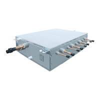
Connection pipe size of Flow Selector unit (default)
Outdoor unit side
(Upstream)
Indoor unit side
(downstream)
Suction gas pipe Discharge gas pipe Liquid pipe Gas pipe Liquid pipe
Ø1-1/2" (Ø38.1) Ø1-1/8" (Ø28.6) Ø7/8" (Ø22.2) Ø5/8" (Ø15.9) Ø3/8" (Ø9.5)
01_1118431101-EN.indd 801_1118431101-EN.indd 8 7/12/2559 BE 9:53 AM7/12/2559 BE 9:53 AM
 Loading...