143
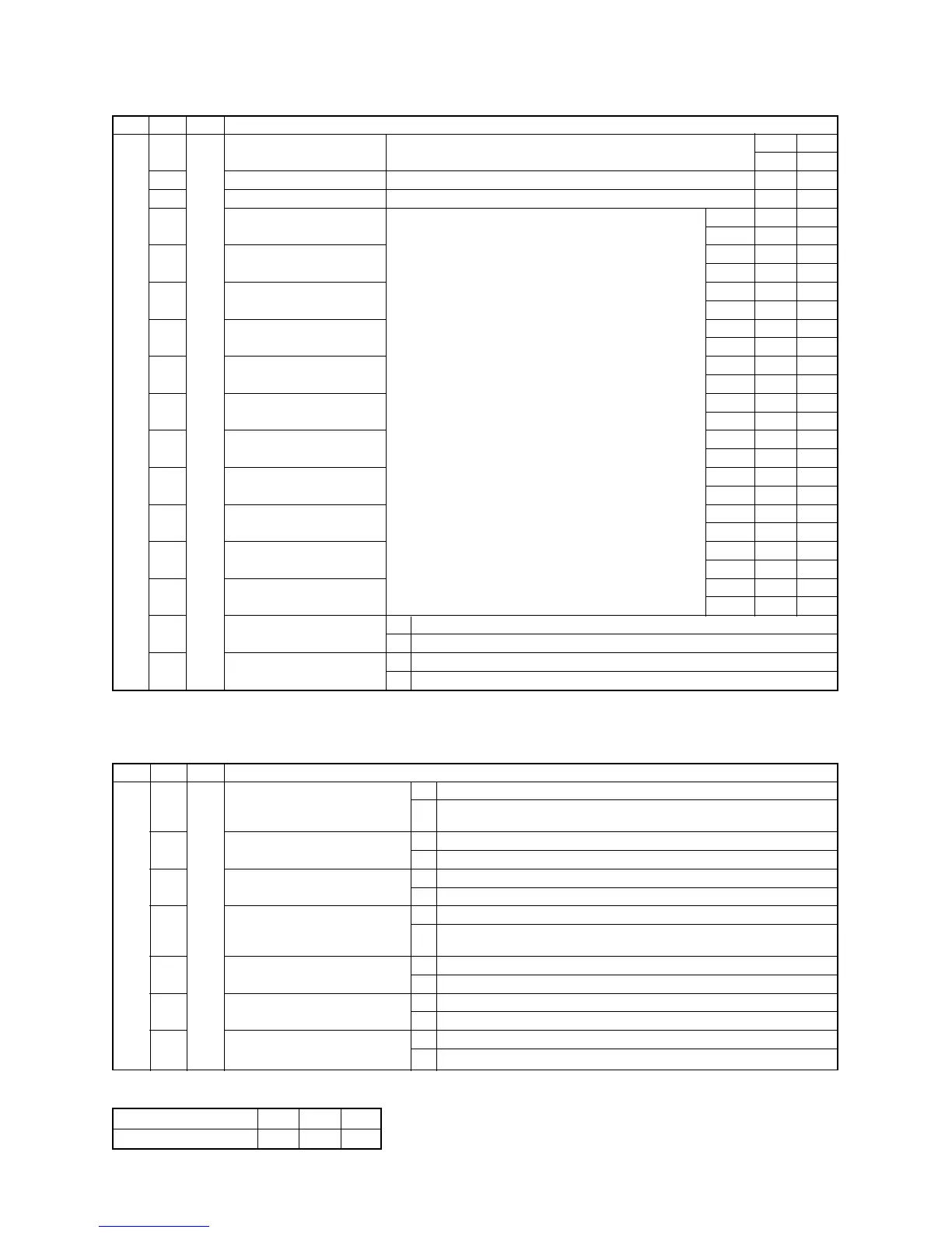
3. Outdoor cycle data display (Displayed on each outdoor unit)
4. Outdoor cycle data display (Displayed on the header unit)
∗ This method is used when information of the follower unit is displayed on 7-segment display of the header unit.
SW01
1
SW02
1
2
3
4
5
6
7
8
9
10
11
12
13
14
15
16
SW03
2
Display contents
Pd pressure data Pd pressure (MPaG) is displayed with decimal data.
(MPaG: Approx. 1/10 value of kg/cm
2
G data)
Ps pressure data Ps pressure (MPaG) is displayed with decimal data.
PL pressure conversion data PL pressure conversion value (MPaG) is displayed with decimal data.
TD1 sensor data Temperature sensor data (°C) is displayed
with decimal notation.
TD2 sensor data
• Symbol display for 1 sec. and data display for 3 sec. are
alternately exchanged.
TS sensor data
• Data is displayed in [∗].
• Negative data is displayed as [– ∗ ∗ ∗ ∗].
TE sensor data
—
TL sensor data
TO sensor data
TK1 sensor data
TK2 sensor data
TK3 sensor data
TK4 sensor data
— A —
B —
— A —
B
AB
P d. ∗. ∗ ∗
P S. ∗. ∗ ∗
P L. ∗. ∗ ∗
Symbol t d 1 1 1
Data ∗∗ ∗. ∗
Symbol t d 2 1 1
Data ∗∗ ∗. ∗
Symbol t S
Data ∗∗ ∗. ∗
Symbol t E
Data ∗∗ ∗. ∗
Symbol ——
Data ——
Symbol t L
Data ∗∗ ∗. ∗
Symbol t o
Data ∗∗ ∗. ∗
Symbol F 1
Data ∗∗ ∗. ∗
Symbol F 2
Data ∗∗ ∗. ∗
Symbol F 3
Data ∗∗ ∗. ∗
Symbol F 4
Data ∗∗ ∗. ∗
SW01
1
SW02
1
2
3
4
5
6
7
SW03
1 to 3
Display contents
Error data A [U. ∗] ∗: SW03 setup number + 1 number (Outdoor unit number U2 to U4)
B Check code is displayed. (Latest check code only)
No check code: [– – –]
Installed compressor type A [U. ∗] ∗: SW03 setup number + 1 number (Outdoor unit number U2 to U4)
B
Outdoor unit HP A [U. ∗] ∗: SW03 setup number + 1 number (Outdoor unit number U2 to U5)
B 8HP: [
…
…
8]. 10HP: [
…
1 0], 5 to 12HP
Compressor operation command A [U. ∗] ∗: SW03 setup number + 1 number (Outdoor unit number U2 to U5)
B No.1 compressor ON: [C10], No.2 compressor ON: [C01]
For unconnected compressor, “ – ” is displayed.
Fan operation mode A [U. ∗] ∗: SW03 setup number + 1 number (Outdoor unit number U2 to U5)
B Stop time: [F
…
0], Mode 31: [F 3 1]
Release signal A [U. ∗] ∗: SW03 setup number + 1 number (Outdoor unit number U2 to U5)
B Normal time: [r
…
…
], Release received: [r
…
1]
Oil level judgment A [U. ∗] ∗: SW03 setup number + 1 number (Outdoor unit number U2 to U5)
B Normal time: [
…
…
…
], Oil shortage: [
…
…
L]
NOTE) The follower unit is setup by exchanging SW03.
SW03
7-segment display A
123
U2 U3 U4
 Loading...