144
5. Indoor unit information data display (Displayed on the header unit only)
SW01
4
5
6
7
8
9
10
11
12
13
SW02
1 to 16
SW03
1 to 3
Display contents
Receiving status of B Receiving time: [
…
…
1], Not received: [
…
…
…
]
indoor BUS communication
Indoor check code B No check code: [– – –]
Indoor horse power B 0. 2, 0. 5, 0. 8,
…
1, 1. 2, 1. 7,
…
2, 2. 5,
…
3, 3. 2,
…
4,
…
5,
…
6,
…
8, 1 0, 1 6, 2 0
Indoor request command B Data is displayed with hexadecimal [
…
…
0 to
…
…
F]
(S code)
Indoor PMV opening data B Data is displayed with hexadecimal
Indoor TA sensor data B Data is displayed with hexadecimal
Indoor TF sensor data B Data is displayed with hexadecimal
Indoor TCJ sensor data B Data is displayed with hexadecimal
Indoor TC1 sensor data B Data is displayed with hexadecimal
Indoor TC2 sensor data B Data is displayed with hexadecimal
NOTE) Indoor address No. is set up by exchanging SW02 and SW03.
SW03
1
2
3
SW02
1 to 16
1 to 16
1 to 16
Indoor address
SW02 setup number
SW02 setup number + 16
SW02 setup number + 32
7-segment display A
[01] to [16]
[17] to [32]
[33] to [48]
6. Outdoor EEPROM write-in error code display (Displayed on the header unit only)
∗ The latest error code written in EEPROM of each outdoor unit is displayed.
(It is used when confirming the error code after power supply has been reset.)
Set SW01 to 03 as shown in the following table, and the push SW04 for 5 seconds or more to display an
error code.
SW01
1
SW02
1
2
3
4
SW03
16
Display contents
The latest error code of the header unit 1 (U1)
The latest error code of the follower unit 1 (U2)
The latest error code of the follower unit 2 (U3)
The latest error code of the follower unit 3 (U4)
7-segment display
AB
E. r 1. – –
E. r 2. – –
E. r 3. – –
E. r 4. – –
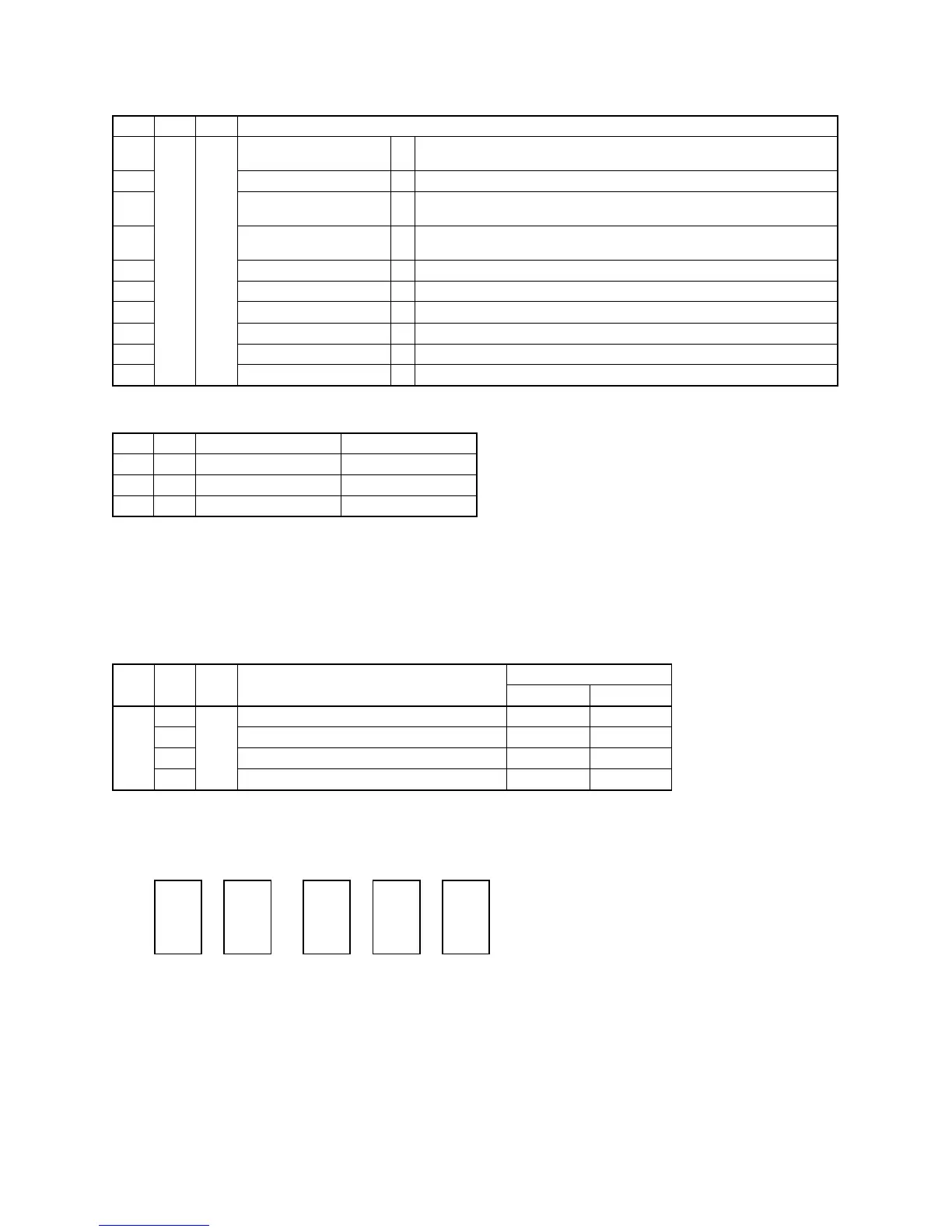
• 7-segment display A, B
The latest error code of the header unit
The latest error code of the follower unit 1
The latest error code of the follower unit 2
The latest error code of the follower unit 3
D602 D603 D604D600 D601
Display A Display B
 Loading...