49
Connection of power supply wire with control wire
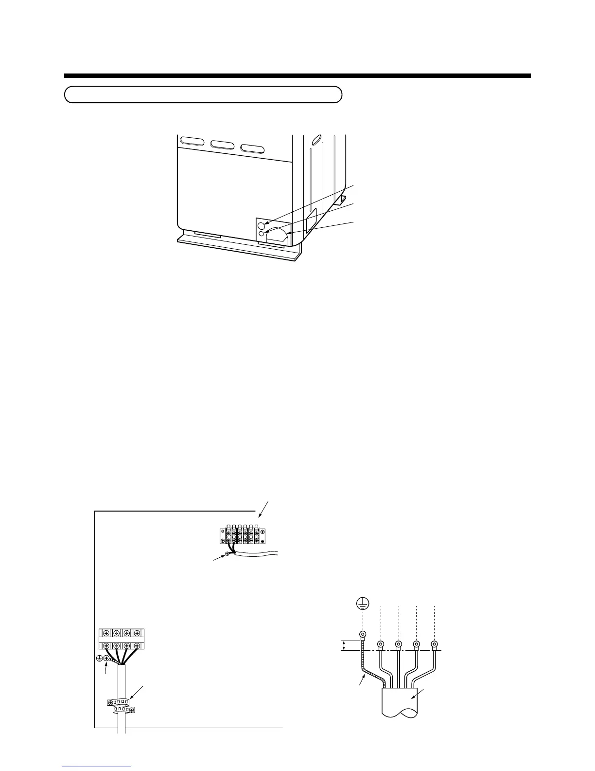
Insert power supply wire and control wire after removing knockout of the piping/wiring panel at front side of the
outdoor unit.
n Power supply wire
1. Connect the power supply wires and earthing wire to the terminal block of the power supply through a notched
section at side of the electric parts box, and fix with a clamp.
2. Bundle the power supply wires using the hole so that they are not out of the notched section of the electric
parts box.
n Control wire
1. Connect the control wire between indoor and outdoor units and the control wire between outdoor units to
(U1 to U4) terminal section through a hole at side of the electric parts box.
2. Use the control wire with 2-core shield wire (1.25mm² or more) in order to prevent noise trouble. (Non-polarity)
NOTE :
1) Be sure to separate the power supply wires and each control wire.
2) Arrange the power supply wires and each control wire so that they do not contact with the bottom surface of the
outdoor unit.
3) A terminal block (U3, U4 terminal blocks) for connecting an optional part “Central remote controller” is provided
on the header unit, so be careful to miswiring.
6
ELECTRIC WIRING
Knockout for power supply wire
Knockout for control wire
Piping/wiring panel
When insert power supply wire
and control wire, protect power supply wire
and control wire from edge after removing knockout.
Earth line
10mm
or more
Power supply wire
L1 L2 L3 N
U1 U2 U3 U4 U5 U6
L1 L2 L3 N
Earth screw
Earth
screw
P.C. board
Power supply
terminal block
( )
U1-U2
U3-U4
U5-U6
: For wiring for control wire between indoor/outdoor unit
: For “Central remote controller etc.”
: Not use this model.
U1-U6 Terminal
Clamp
 Loading...