– 202 –
Yes
No
Yes
No
* 380-415V ± 10%
Yes
No
Yes
No
No
Yes
[H01]
V
U
W
[F29]
(Power ON)
(Repetition)
(Approx. 3 minutes) (Approx. 1 minute)
Yes
No
[F31]
esuaCedoc kcehC Check code name
esuaCedo
c
k
ceh
C
Check code name
esuaCedoc kcehC Check code name
Indoor other error
Indoor P.C. board error
This error is detected during operation of air conditioner of IC10 non-volatile memory (EEPROM) on
indoor unit P.C.board. Replace service P.C. board.
* If EEPROM was not inserted when power was turned on or it is absolutely impossible to read/write
EEPROM data, the automatic address mode is repeated. In this case, [97 error] is displayed on AI-NET
central controller.
[SET DATA]
is displayed
on remote
controller.
[SET DATA]
disappears.
LED (D02) 1Hz
flashes for approx.
10 seconds on
indoor unit P.C.
board.
Reboot (Reset)
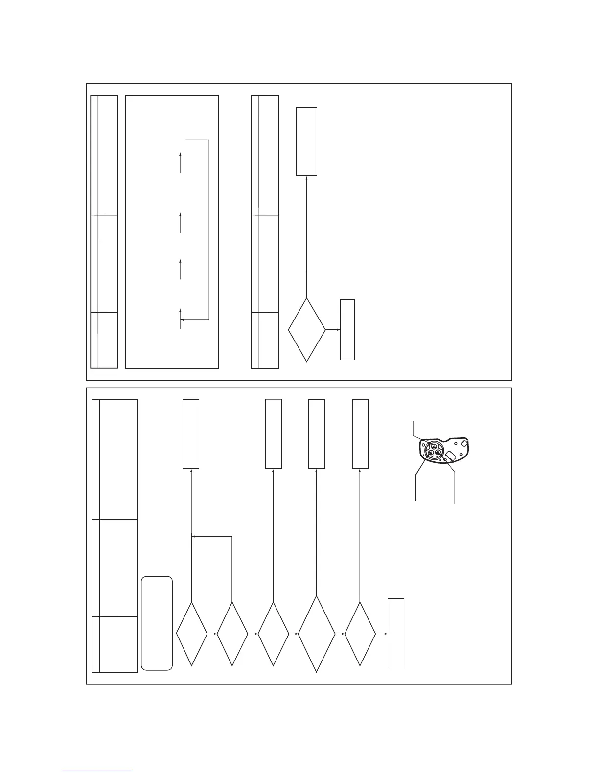
Outdoor EEPROM error
1. Outdoor unit power error (Voltage, noise, etc.)
2. Outdoor I/F P.C. board error
Is there any trouble
of outdoor unit
power supply?
Is power voltage
of outdoor unit
normal?
Does voltage
drop occur when
other compressor
starts?
Is winding
resistance between
phases of corresponding
compressor normal?
(Note 1)
Is not it an abnormal
overload?
Is connection
of wiring or connection of
connector on A3-IPDU P.C.
board normal?
Check power voltage and line.
Correct power line.
Check external noise, etc.
Check I/F P.C. board.
Correct power line.
Correct connector connection
or wiring.
Compressor error (Motor
burning, etc.)
Correct cause of overload.
Check IPDU P.C. board.
Compressor breakdown
Rotor-stop conduction has
occurred.
1. Outdoor unit power line error
2. Compressor circuit system error
3. Compressor error
4. Abnormal overload in operation
5. A3-IPDU P.C. board error
Sub-code:
01: Compressor 1,
02: Compressor 2,
03: Compressor 3
Take off lead wire of compressor.
1. Check resistance between windings:
It is normal if there are 0.1Ω to 0.4Ω
.
2. Check insulation between outdoor cabinet and terminal:
It is normal if there are 10M
Ω
or more.
Note 1
After checking the output, when connecting the compressor
lead again to the compressor terminal, check surely there is
no distortion on the Fasten receptacle terminal.
If it is loosened, caulk it with pinchers, etc and then connect
lead to the terminal firmly.
Details of compressor
power connecting section
 Loading...


