– 205 –
Yes
No
No
No stagnation
Yes
No
Error
Yes
Yes
No
No leakage or clogging
No clogging
No clogging
Stagnation
No error
Clogging
Clogging
Clogging
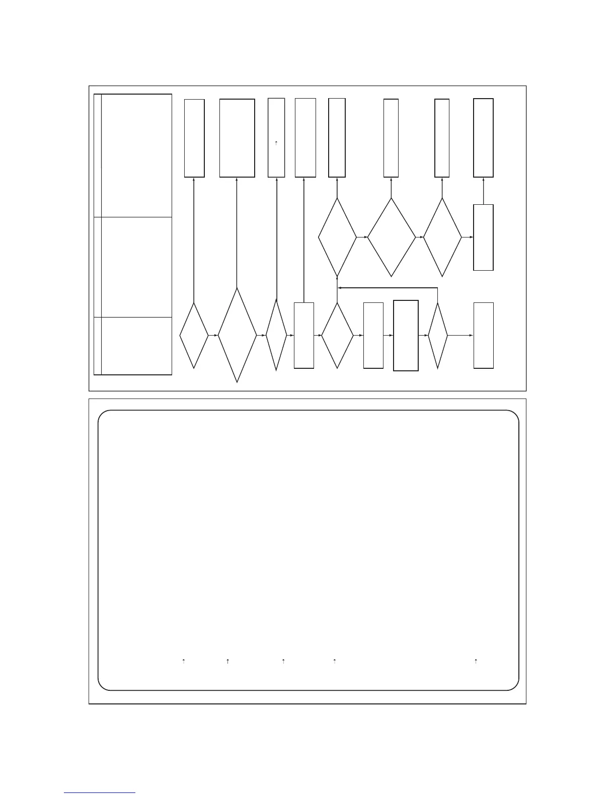
[H07]
esuaCedoc kcehC Check code name
Oil level down detection
protection
1. Valves of balance pipes closed. (On all outdoor
units in a line)
2. Miswiring or misinstallation of TK1 to TK5 sensors
3. TK1 to TK5 sensor error
4. Gas leak or oil leak in a line
5. Refrigerant stagnation of compressor case
6. SV3A, 3B, 3C, 3D, 3E, 3F valve error
7. Clogging of oil return circuit from oil separator
8. Clogging of oil-equation circuit system
Are balance
pipe valves of all outdoor
units in same line fully
opened?
Are TK1, TK2,
TK3, TK4 and TK5 sensors of
the error-detected unit correctly
connected? Are all the sensors
properly connected?
Are
characteristics of TK1 to
TK5 of error-detected unit
normal?
Check refrigerant
stagnation in
compressor.
(*1) Check leakage of
valves (SV3A, SV3C) and
clogging (SV3B, SV3E,
SV3F).
(*2) Check
clogging of oil return
circuit from oil
separator. (Capillary
tube, strainer)
Check clogging of
SV3D valve.
Check clogging
of solenoid valves (SV3A,
SV3C) of all outdoor units
in the same line. (*3)
Are all oil levels
correct?
Open balance pipe valves
fully, reset power supply,
and start operation.
Sensor error
Replace
Specify gas leak position and
repair it.
(Recharging, refill oil)
Replace faulty part.
Replace faulty part.
Replace faulty part.
Replace faulty part.
Check gas leak of all outdoor
units in the same line and
check soaked oil in them.
Correct refrigerant stagnation
in compressor, reset power
supply, and start the operation.
Clear cause of stagnation.
Check clogging of oil
equalization circuit. (*4)
Check oil level judgment of each unit.
The check result is indicated on the 7-
segment display by setting
[SW01/02/03] to [1/16/1].
Correct miswiring and misinstallation.
TK1: CN531, black
TK2: CN532, green
TK3: CN533, pink
TK4: CN534, yellow
TK5: CN535, red
Indoor/outdoor PMV error (Cause of refrigerant stagnation),
discharge check valve error, etc.
(Reference) When refrigerant stagnates in compressor shell, the oil level shortage may be
Leakage or
clogging
In some cases, it may be difficult to check the leakage of clogging in the following condition of refrigerant
stagnation in low ambient temperature condition.
In this case, take a longer operating time prior to check.
(Criterion: Discharge temperature of TD1 and TD2 are 60°C or higher)
(*1) Checking leakage and clogging on solenoid valves
a) Leakage check for SV3A valve (For multiple outdoor unit system)
• Turn off the power supply, take off connector of SV3A valve, and then start a test operation after
power-ON.
• Check the temperature change at secondary side of SV3A valve during operation . ((1) in the figure.)
If temperature is raised, leakage occurs in the SV3A valve. Replace SV3A valve.
b) Leakage check for SV3C valve
• Turn off the power supply, take off connector of SV3C valve, and then start a test operation after
power-ON.
• After operation for several minutes, check temperature at secondary side of SV3C valve. ((2) in the
figure.)
If temperature is high (equivalent to discharge temperature TD), leakage occurs in the SV3C valve.
Replace SV3C valve.
(Even if leakage does not occur in the SV3C valve, temperature of SV3C valve at secondary side
rises during operation. But the temperature is lower than TD when there is no leakage.)
c) Leakage check for SV3F valve (For multiple outdoor unit system)
• Turn off the power supply, take off connector of SV3F valve, and then start a test operation after
power-ON.
• Check the temperature change at secondary side of SV3F valve during operation . ((3) in the figure.)
If temperature is raised, leakage occurs in the SV3A valve. Replace SV3A valve.
d) Clogging check for SV3B valve (For multiple outdoor unit system)
• While outdoor unit is operated, set up SW01/02/03 = [2] [1] [3] (7-segment display [Hr] [... ... ...]), and
push SW04 for 2 seconds or more.
• Set up SW02 = [10], and turn on SV3A, SV3B, SV3C valves. (7-segment display [Hr] [... 3 -])
• While outdoor units are operating, check temperature change at secondary side of SV3B valve. ((4) in
the figure.)
If temperature does not rise (equivalent to suction temperature), it is a clogging of SV3B valve.
Replace SV3B valve.
e) Clogging for SV3E valve
Reset the power supply.
↓
Using "Valve forced open/close function" of the outdoor unit, check ON/OFF operation (Sound, coil
surface temp up) of SV3E valve is performed.
↓
Start test operation in COOL or HEAT mode.
↓
After operation for several minutes, check the pipe temperature at the secondary side of SV3E valve
whether temperature changes or not. If it is equivalent to outside temperature, clogging of SV3E is
considered. ((5) in the figure.)
(Reference)
If SV3E valve is clogged, temperature does not change at all sensors (TK1, TK2, TK3, TK4 and TK5).
f) Clogging check for SV3F valve
• While outdoor unit is operated, set up SW01/02/03 = [2] [1] [3] (7-segment display [Hr] [... ... ...]), and
push SW04 for 2 seconds or more.
• Set up SW02 = [8], and turn on SV3C, SV3E, SV3F valves. (7-segment display [Hr] [... 3 C])
• While outdoor units are operating, check temperature change at secondary side of SV3F valve. ((3) in
the figure.)
If temperature does not rise (equivalent to suction temperature), it is a clogging of SV3F valve.
Replace SV3F valve.
*See “Outdoor unit temperature sensor
characteristics” on “8-9. Sensor Characteristics”.
 Loading...


