– 212 –
[L17]
No
Yes
[L20]
Yes
No
Yes
No
[L28]
e
sua
C
edo
c k
cehC Check code name
esuaC
edo
c kcehC
Check code name
e
sua
C
edo
c k
cehC Check code name
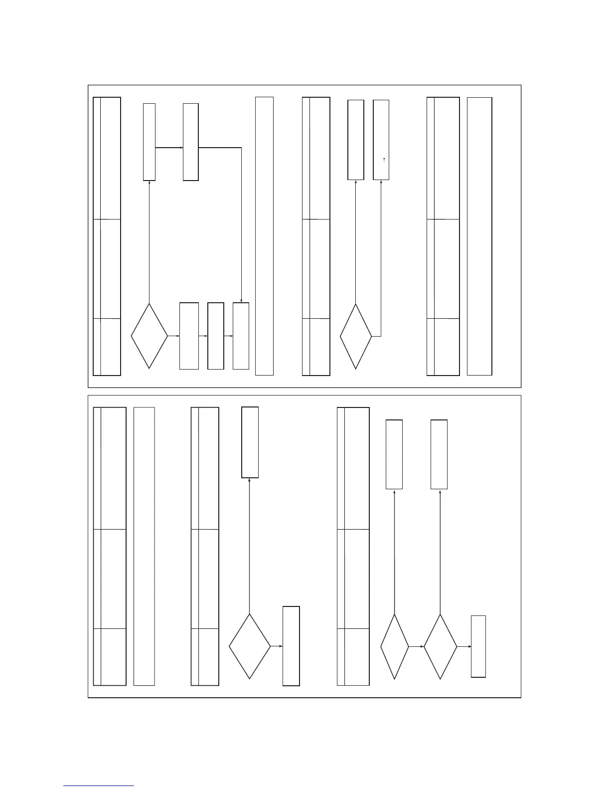
An SMMS-i outdoor unit (SMMS4 series unit) and an
outdoor unit of SMMS3 series or older are connected.
Incompatible combination of
outdoor units
Central control addresses are duplicated.
Duplicated central control
addresses
Quantity over of connected
outdoor units
An SMMS-i outdoor unit (SMMS4 series unit) cannot be connected with an outdoor unit of SMMS3 series or older.
Use it with another SMMS-i unit.
Are not two
or more central
control devices which have
same network address
connected?
Is the number of
the connected outdoor
units 4 or less?
Is the
communication
line between outdoor
units correctly
connected?
Correct the network address
of the central control system.
Max. 4 outdoor units are
connectable for one system.
Correct connection of the
communication line.
Check I/F P.C. board.
Check the network adaptor on the
indoor P.C. board.
1. Quantity over of connected outdoor units.
2. Connection error of communication line between
outdoor units
3. Outdoor I/F P.C. board error
[L08]
Yes
No
No
Yes
[L09]
[L10]
esuaCedoc kcehC Check code name
esuaCedoc kcehC Check code name
esuaCedoc kcehC Check code name
I/F P.C. board A'ssy service for the outdoor unit is common to this series. A setup for model selection different
from that for P.C. board with trouble is necessary. Set up a model based upon the P.C. board A'ssy exchange
procedure.
Indoor unit address is unset
Indoor group / address unset
Indoor unit's capacity is unset
Indoor capacity unset
On the outdoor IF P.C. board for service, the model
selecting jumper has not been set up so as to match
with the model.
Outdoor capacity unset
Are powers of all the
indoor units turned on?
Are capacity setups of
indoor units unset?
Turn on the power of indoor units.
Turn on the power of outdoor
unit again.
Set up capacity data of indoor unit.
(Setup CODE No. (DN) = 11)
Check indoor P.C. board.
Defect
Replace
Re-execute address setup.
(Refer to "Address setup".)
Disconnect connectors
between [U1, U2] and [U3, U4].
Clear addresses.
(Refer to "Address clear".)
Note) This code is displayed when the power is turned on at the first time after installation. (Because the address
is not yet set up)
 Loading...


