EasyManua.ls Logo

Toshiba MV13M3C User Manual

Toshiba MV13M3C
63 pages
To Next Page IconTo Next Page
Page #1 background imageLoading...
Page #1 background image
SERVICE MANUAL
COLOR TELEVISION/
VIDEO CASSETTE RECORDER
FILE NO. 140-200126
MV13M3C
Question and Answer IconNeed help?

Do you have a question about the Toshiba MV13M3C and is the answer not in the manual?

Toshiba MV13M3C Specifications

General IconGeneral
BrandToshiba
ModelMV13M3C
CategoryTV VCR Combo
Screen Size13 inches
Screen TypeCRT
TunerNTSC
Remote ControlYes
InputsComposite

Summary

SERVICING NOTICES ON CHECKING

AVOID AN ELECTRIC SHOCK

High voltage parts inside require caution to avoid electric shock.

PERFORM A SAFETY CHECK AFTER SERVICING

Conduct safety checks, including insulation resistance, post-service.

HOW TO ORDER PARTS

MODEL NUMBER AND VERSION LETTER

Identify the model and version for ordering parts.

TAPE REMOVAL METHOD AT NO POWER SUPPLY

GENERAL SPECIFICATIONS

TV

Specifications related to the television display and components.

VCR

Specifications for the video cassette recorder section.

On Screen Display

Features and settings available on the On-Screen Display menu.

Remote Control Unit

Details about the remote control unit, keys, and functions.

DISASSEMBLY INSTRUCTIONS

1-2: CRT PCB

Steps for removing the CRT PCB with a safety caution.

1-4: DECK CHASSIS AND SYSCON PCB

Steps to remove the deck chassis and SYSCON PCB.

2-2: CASSETTE HOLDER ASS'Y

Steps for removing the cassette holder assembly.

2-11: A/C HEAD

Steps for removing the A/C head assembly.

REMOVAL OF ANODE CAP

REMOVAL

Steps for safely discharging and removing the anode cap.

REMOVAL AND INSTALLATION OF FLAT PACKAGE IC

REMOVAL

Process for removing a flat package IC using desoldering tools.

SERVICE MODE LIST

Set Key / Remocon Key / Operations

Mapping buttons to service mode functions and operations.

PREVENTIVE CHECKS AND SERVICE INTERVALS

CONFIRMATION OF HOURS USED

Procedure to check the unit's total power-on and play/rec hours.

CLEANING

1. AUDIO CONTROL HEAD

How to clean the audio control and full erase heads.

WHEN REPLACING EEPROM (MEMORY) IC

Procedure

Steps to enter data set mode and input new EEPROM data.

SERVICING FIXTURES AND TOOLS

How to use the Servicing Fixture

Instructions for using specific servicing fixtures.

MECHANICAL ADJUSTMENTS

1-1: CONFIRMATION AND ADJUSTMENT OF REEL DISK HEIGHT

Adjusting reel disk height using specific jigs.

1-3: CONFIRMATION OF PLAYBACK TORQUE AND BACK TENSION TORQUE DURING PLAYBACK

Measuring playback and back tension torque with a tape.

2. CONFIRMATION AND ADJUSTMENT OF TAPE RUNNING MECHANISM

Verifying and adjusting the tape running mechanism.

2-2: CONFIRMATION AND ADJUSTMENT OF AUDIO/CONTROL HEAD

Adjusting the audio/control head for proper signal playback.

MECHANISM ADJUSTMENT PARTS LOCATION GUIDE

ELECTRICAL ADJUSTMENTS

1. BEFORE MAKING ELECTRICAL ADJUSTMENTS

Precautions and preparation before performing adjustments.

2. BASIC ADJUSTMENTS (VCR SECTION)

Basic adjustments for the VCR section.

2-6: WHITE BALANCE

Adjusting white balance for accurate color reproduction.

2-13: SUB TINT

Adjusting sub tint for correct color hue.

ELECTRICAL ADJUSTMENT PARTS LOCATION GUIDE

PURITY AND CONVERGENCE ADJUSTMENTS

4-1: STATIC CONVERGENCE (ROUGH ADJUSTMENT)

Performing rough adjustments for static convergence.

4-4: DYNAMIC CONVERGENCE

Performing dynamic convergence adjustments.

WAVEFORMS

Y/C/AUDIO/CCD/HEAD AMP

Waveform examples for Y/C, Audio, CCD, and Head Amplifier circuits.

MICON

Waveform examples for the MICON (microcontroller) signals.

MECHANICAL EXPLODED VIEW

CHASSIS EXPLODED VIEW (TOP VIEW)

MECHANICAL REPLACEMENT PARTS LIST

ELECTRICAL REPLACEMENT PARTS LIST

RESISTORS

List of replacement resistors with their specifications.

CAPACITORS

List of replacement capacitors with their specifications.

ICS

List of replacement ICs with their part numbers.

TRANSISTORS

List of replacement transistors with their specifications.
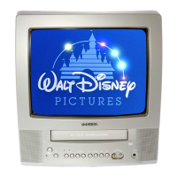
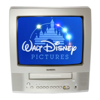
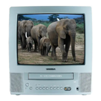
TV BLOCK DIAGRAM

Y/C/AUDIO/CCD/HEAD AMP BLOCK DIAGRAM

MICON/AV/IN/OUT BLOCK DIAGRAM

PRINTED CIRCUIT BOARDS SYSCON/CRT (INSERTED PARTS) SOLDER SIDE

IN/OUT SCHEMATIC DIAGRAM (SYSCON PCB)

AV SCHEMATIC DIAGRAM (SYSCON PCB)

CHROMA/IF SCHEMATIC DIAGRAM (SYSCON PCB)

SOUND AMP SCHEMATIC DIAGRAM (SYSCON PCB)

POWER SCHEMATIC DIAGRAM (SYSCON PCB)

DEFLECTION SCHEMATIC DIAGRAM (SYSCON PCB)

CRT SCHEMATIC DIAGRAM (CRT PCB)

INTERCONNECTION DIAGRAM

Related product manuals