Do you have a question about the Toshiba RAS-07SKHP-E and is the answer not in the manual?
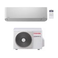
| Type | Split System |
|---|---|
| Cooling Capacity | 2.0 kW |
| Heating Capacity | 2.5 kW |
| Energy Efficiency Ratio (EER) | 3.21 |
| Refrigerant | R32 |
| Indoor Unit Dimensions (W x H x D) | 740 x 250 x 195 mm |
| Outdoor Unit Dimensions (W x H x D) | 660 x 530 x 240 mm |
| Weight (Indoor Unit) | 9 kg |
| Power Supply | 220-240V, 50Hz |
| Noise Level (Outdoor) | 48 dB(A) |
Detailed technical specifications for cooling and heating modes, power, and performance.
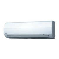
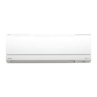
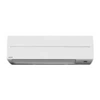
Physical dimensions, net weight, and airflow rates for the indoor unit.
Physical dimensions, net weight, and key components of the outdoor unit.
Detailed diagram showing the physical layout and components of the indoor unit.
Detailed diagram showing the physical layout and components of the outdoor unit.
Diagram illustrating the electrical connections between internal and external components.
List and specifications of electrical components used in the indoor unit.
List and specifications of electrical components used in the outdoor unit.
Visual representation of the refrigerant path and operating conditions for cooling/heating.
Diagram illustrating the MCU's control functions, signal flow, and operations.
Explanation of remote control buttons, indicators, and display features.
Description of various operating modes like Cooling, Heating, Dry, Fan, and Auto.
Details on limit controls, defrost, current limit, and auto-restart functions.
Critical safety guidelines for unit installation to prevent hazards and ensure compliance.
Procedures for mounting, connecting, and securing the indoor unit to the wall.
Procedures for placing, connecting, and securing the outdoor unit to its base.
Initial checks for power supply, connections, and common operational failures.
Methods for identifying faults using unit indicators, lamps, and self-diagnosis codes.
Step-by-step diagnostic guides for resolving specific operational problems.
Step-by-step procedures for disassembling and replacing parts within the indoor unit.
Step-by-step procedures for disassembling and replacing parts within the outdoor unit.
Illustrated breakdown of indoor unit components with part numbers and locations.
Illustrated breakdown of outdoor unit components with part numbers and locations.