Do you have a question about the Toshiba RAS-10SAV2-E and is the answer not in the manual?
| Brand | Toshiba |
|---|---|
| Model | RAS-10SAV2-E |
| Category | Air Conditioner |
| Language | English |
Explains DANGER, WARNING, CAUTION symbols, and general safety precautions.
Precautions for R410A installation and handling.
Lists capacities, power, noise, and dimensions for various models.
Shows multi-split compatibility and operational characteristics.
Precautions for handling R410A refrigerant during installation and service.
Requirements for copper pipes, joints, and materials.
Lists exclusive and general tools necessary for R410A installation.
Step-by-step guide for adding refrigerant to the system.
Details on types of brazing fillers and the use of flux.
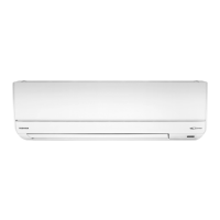
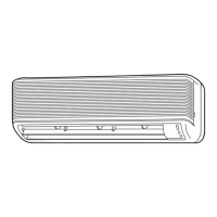
Diagrams showing indoor unit parts and dimensions.
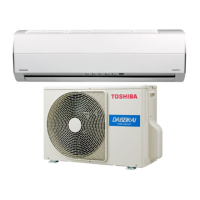
Diagrams showing outdoor unit components and dimensions.
Electrical connection schematic for specific models.
Electrical connection schematic for specific models.
List of electrical components for indoor units.
List of electrical components for outdoor units.
Diagram illustrating refrigerant flow for specific models.
Diagram illustrating refrigerant flow for specific models.
Performance data at various temperature and operating conditions.
Schematic of the indoor unit's control system.
Schematic of the outdoor unit's control system.
Overview of how the air conditioner's control system operates.
Lists various operation modes and functions described in the manual.
Explanation of basic ON/OFF and mode selection.
Describes the cooling, heating, and auto operation modes.
Specifics of the dehumidification mode.
Details on indoor fan speed control during cooling.
Details on indoor fan speed control during heating.
Explanation of how the outdoor fan speed is managed.
How cooling and heating capacity are adjusted.
Over-current protection for the compressor.
Protective control to prevent freezing or over-pressure.
Process for removing frost from the outdoor unit.
How to adjust the airflow direction.
Control procedures for the lower louvers.
Control procedures for the upper louvers.
Explanation of the energy-saving ECO mode.
Steps for performing a test run of the unit.
Compressor speed adjustment based on discharge temperature.
Regulation of refrigerant flow using the PMV.
How the self-cleaning feature operates.
Procedures for managing the self-cleaning function.
Configuring remote control for multiple indoor units.
Details on quiet operation and comfort sleep modes.
Timer settings and filter maintenance alert.
Automated comfort and high-performance modes.
Adjusting the set temperature offset.
Function for reducing outdoor unit noise levels.
Procedures for configuring and disabling the auto restart feature.
Overview of remote buttons, display, and functions.
How to use ONE-TOUCH, AUTO, COOL/HEAT modes.
Details on DRY, Hi-POWER, ECO, and Timer operations.
Covers PRESET, QUIET, SLEEP, FILTER RESET functions.
Basic checks for common issues like no operation or low cooling/heating.
Procedure for managing remote control signals for multiple units.
Procedure to change the brightness of the unit's display.
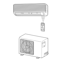
Visual guide showing placement and clearances for units.
Details on included and optional items for installation.
List of packaged accessories and installation parts.
Comparison of tools needed for R410A vs R22.
Recommended placement criteria for the indoor unit.
Procedures for preparing the mounting plate and wall.
Step-by-step guide for installing the indoor unit.
Special installation instructions for wall-recessed units.
Recommended placement criteria for the outdoor unit.
Advice for installing in regions with snow and low temperatures.
How to manage water drainage from the outdoor unit.
Guide to connecting refrigerant pipes and flaring techniques.
Process for removing air and moisture from the system.
Guidelines for electrical connections and power supply.
How to perform a gas leak test on the system.
Configuring remote control selector switches.
Managing remote signals for separate indoor units.
Steps for performing a test run of the unit.
Setting up and configuring the auto restart feature.
Safety guidelines for working with the inverter.
General approach to identifying and diagnosing faults.
Safety measures when inspecting the control board.
Verifying power supply and basic operational status.
Distinguishing normal functions from potential faults.
Initial methods for fault diagnosis.
Diagnosing faults by interpreting LED codes on the indoor unit.
Accessing diagnostic information via the remote controller.
Steps to enter and operate the remote controller in service mode.
Safety measures and post-service steps.
Detailed explanations of error codes and their causes.
Diagnosing indoor unit issues based on observed symptoms.
Specific steps for diagnosing indoor fan motor problems.
Diagnosing why the indoor fan motor starts automatically.
Diagnosing problems related to the remote control.
Troubleshooting issues with interconnecting and serial signal wires.
Specific troubleshooting steps for error codes 1C and 1E.
Overview of diagnosing the outdoor unit's inverter assembly.
Procedure for inspecting the indoor unit's P.C. board.
Step-by-step checks for various electronic parts.
Visual layout of components on the P.C. board.
Resistance measurements for indoor sensors and motors.
Resistance measurements for outdoor components.
Methods to determine the condition of the outdoor fan motor.
Steps for removing and replacing the front panel.
Steps for replacing the E-box assembly.
Procedures for replacing the heat exchanger and louvers.
Steps for replacing these specific components.
Procedures for replacing the turbo fan and fan motor.
Additional steps for fan motor replacement.
Steps for replacing the microcomputer.
General disassembly and reassembly steps for the outdoor unit.
Steps for replacing the front cabinet.
Steps for replacing the inverter assembly.
Steps for replacing the control board assembly.
Steps for replacing side cabinet and fan motor.
Steps for replacing the compressor and reactor.
Steps for replacing the expansion valve coil and fan guard.
Instructions for installing temperature sensors.
Details on replacement parts and important notes for sensors.
Disassembly and assembly steps for the RAS-18SAV-E model.
Steps for replacing the front cabinet on this model.
Steps for replacing the inverter assembly on this model.
Steps for replacing the control board assembly on this model.
Steps for replacing side cabinet and fan motor on this model.
Steps for replacing the compressor and reactor on this model.
Steps for replacing valve coil and fan guard on this model.
Instructions for installing temperature sensors for this model.
Diagram and list for indoor unit components.
Diagram and list for indoor unit electronic parts.
Diagram and list for outdoor unit components.
Diagram of PC board layout for specific models.
Diagram of PC board layout for a specific model.
Diagram of PC board layout for a specific model.