EasyManua.ls Logo

Toshiba RAS-10SAVP-E User Manual

Toshiba RAS-10SAVP-E
119 pages
To Next Page IconTo Next Page
Page #1 background imageLoading...
Page #1 background image
R410A
FILE NO. A06-011
SERVICE MANUAL
AIR-CONDITIONER
SPLIT TYPE
Indoor Unit Outdoor Unit
<High Wall, Heat Pump Type> <Heat Pump Type>
(Standard Type)
RAS-B10SKVP-E RAS-10SAVP-E
RAS-B13SKVP-E RAS-13SAVP-E
RAS-B16SKVP-E RAS-16SAVP-E
(North Europe Type)
RAS-10SKVP-ND RAS-10SAVP-ND
RAS-13SKVP-ND RAS-13SAVP-ND
RAS-16SKVP-ND RAS-16SAVP-ND
PRINTED IN JAPAN, Fub, 2007 ToMo
Toshiba ilmalämpöpumppujen myynti, huolto ja asennus: Jäähdytinpalvelu RefGroup Oy, Vantaa
www.ilmalämpöpumput.com

Table of Contents

Question and Answer IconNeed help?

Do you have a question about the Toshiba RAS-10SAVP-E and is the answer not in the manual?

Toshiba RAS-10SAVP-E Specifications

General IconGeneral
BrandToshiba
ModelRAS-10SAVP-E
CategoryAir Conditioner
LanguageEnglish

Summary

Safety Precautions

General Safety Precautions

Essential safety guidelines to follow before, during, and after servicing the unit.

Refrigerant R410A Handling

Wiring Diagrams

Indoor and Outdoor Unit Wiring Diagrams

Detailed wiring diagrams for both indoor and outdoor units, illustrating component connections and power supply.

Refrigerant Cycle Diagram

Control Block Diagrams

Indoor and Outdoor Unit Control Block Diagrams

Block diagrams illustrating the control logic and functions of both indoor and outdoor units.

Operation Description

9-1. Outline of Air Conditioner Control

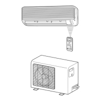
Overview of the air conditioner's control system, roles of indoor/outdoor units, and component functions.

Installation Procedure

10-1. Installation Safety and Tools

Essential safety precautions, optional parts, and required tools for installation.

10-5. Test Operation and Troubleshooting

Procedures for gas leak test, test operation, auto restart setting, and diagnosing incorrect operation.

How to Diagnose the Trouble

11-3. LED Flashing and Remote Self-Diagnosis

Interpreting indoor unit LED patterns and using remote controller self-diagnosis for fault identification.

11-8. Outdoor Unit and Inverter Diagnosis

Flowcharts for diagnosing outdoor unit and inverter assembly issues, including fan motor and P.C. board checks.

How to Replace the Main Parts

Related product manuals