FILE NO. SVM-06006
7. OPERATION DESCRIPTION
7-1-1. Louver control
(1) Vertical air flow louver
Position of veritcal air flow louver is automatically
controlled according to the operation mode.
Besides, position of vertical air flow louver can be
arbitrarily set by pressing [FIX] button.
The louver position which is set by [FIX] button is
stored in the microcomputer, and the louver is
automatically set at the stored position for the next
operation.
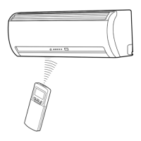
(2) Swing
If [SWING] button is pressed when the indoor unit
is in operation, the vertical air flow louver starts
swinging. When [FIX] button is pressed, it stops
swinging.
7-1-2. Indoor fan control (AC Fan motor)
(1) The indoor fan is operated by the stepless speed
change AC motor.
(2) For air flow level, speed of the indoor fan motor is
controlled in five steps (LOW, LOW
+
, MED, MED
+
and HIGH). If AUTO mode is selected, the fan
motor speed is automatically controlled by the
difference between the preset temperature and
the room temperature.
7-1. Outline of Air Conditioner Control
This is a fixed capacity type air conditioner, which uses
a AC motor for an indoor fan. The AC motor drive
circuit is mounted in the indoor unit. And electrical
parts which operate the compressor and the outdoor
fan motor, are mounted in the outdoor unit.
The air conditioner is mainly controlled by the indoor
unit controller. The controller operates the indoor fan
motor based upon commands transmitted by the
remote control and transfers the operation commands
to the outdoor unit controller.
The outdoor unit controller receives operation
commands from the indoor unit, and operates the
outdoor fan motor and the compressor.
(1) Role of indoor unit controller
The indoor unit controller receives the operation
commands from the remote control and executes
them.
• Temperature measurement at the air inlet of the
indoor heat exchanger by the indoor
temperature sensor
• Temperature setting of the indoor heat
exchanger by the heat exchanger sensor
• Louver motor control
• Indoor fan motor operation control
• LED display control
• Transferring of operation commands to the
outdoor unit
• Receiving of information of the operation status
and judging of the information or indication of
error
(2) Role of outdoor unit controller
The outdoor unit controller receives the operation
commands from the indoor controller and
executes them.
• Compressor operation
control
• Operation control of
outdoor fan motor
• Turning off the compressor and outdoor fan
when the outdoor unit receives the shutdown
command
• Defrost control in heating operation
(Temperature measurement by the outdoor heat
exchanger and control for the four-way valve
and the outdoor fan motor) *Heat pump Model
only
Operations according
to the commands
from the indoor unit
LOW
+
=
MED
+
=
LOW+MED
2
MED+HIGH
2
Table 7-1-1
− 22 −
FAN TAP
Cooling UH H M+
L+
L- SUL/SL-
OPERATION
Fan only
H
M
L
L-
Dry
M
L
L- UL SUL
MODE
Heat
UH H
M+
L
RAS-18UFHP Series
rpm
1060
1030
900
950 820
Air flow volume (m
3
/h)
800
770 720
680
700
600
RAS-24UFHP Series
rpm
920
750
860
Air flow volume (m
3
/h)
810
930
750
660
440
410
rpm
1210
860
600
Air flow volume (m
3
/h)
930 660
410
Model
830
RAS-18UFP Series
rpm
Air flow v
RAS-24UFP Series
olume (m
3
SUL/SL-
/h)
UL
1120
L+
1090
M+
−
M
1000
L+
820
L
L-
M
1090
L+
1210
L
1000
690
600
480
640
480
600
690
640
440
650
450
450
700
490
490
700
650
800
580
580
850
650
650
850
800
−
−
−
−
−
−
−
−
970
500
1170
900
1170
900
800
1060
1120
830
−
−
770
1030
−
−
320
−
760
1020
540
350
−
−
 Loading...