Do you have a question about the Toshiba RAS-24GKP-ES2 and is the answer not in the manual?
Technical specifications including capacity, power consumption, noise levels, and dimensions.
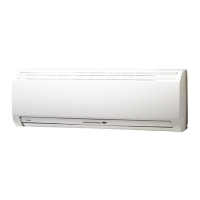
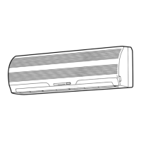
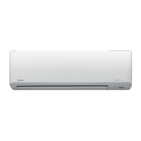
Visual diagrams and dimensions for the indoor unit assembly and components.
Diagrams and dimensions for the 24 Class outdoor unit, showing key parts.
Diagrams and dimensions for the 18 Class outdoor unit, highlighting its structure.
Electrical schematic detailing connections for specific model series.
Electrical schematic detailing connections for specific model series.
Electrical schematic detailing connections for specific model series.
Electrical schematic detailing connections for specific model series.
List of internal electrical components for indoor units and their specifications.
List of external electrical components for outdoor unit models.
List of external electrical components for outdoor unit models.
List of external electrical components for outdoor unit models.
List of external electrical components for outdoor unit models.
Diagram illustrating refrigerant flow, pressure, and temperature conditions.
Diagram illustrating refrigerant flow, pressure, and temperature conditions.
Diagram illustrating refrigerant flow, pressure, and temperature conditions.
Diagram illustrating refrigerant flow, pressure, and temperature conditions.
Functional block diagram outlining the air conditioner's control logic and components.
Functional block diagram outlining the air conditioner's control logic and components.
Explains the roles of indoor and outdoor controllers and system logic.
Detailed description of various operational modes and circuit functions.
Instructions and effects of activating the Hi POWER mode for enhanced cooling/heating.
Explanation of the defrost cycle operation in heating mode.
Guide on setting and managing the auto-restart feature after power loss.
Explanation of the self-cleaning mode for moisture removal and mold prevention.
Critical safety guidelines and warnings before and during installation.
Visual guides for unit placement, piping, and drain hose routing.
Detailed steps for mounting and connecting the indoor unit.
Guidelines for selecting the installation site and mounting the outdoor unit.
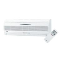
Procedure for setting remote control selector switches for multi-unit systems.
Essential initial checks for power supply and basic operational status.
Methods for diagnosing faults using unit indicators and basic checks.
Procedure for accessing and interpreting self-diagnosis codes on the remote control.
Step-by-step troubleshooting guide for common indoor unit issues.
Diagnosing issues related to interconnect and serial signal wiring.
Instructions for disassembling and replacing components of the indoor unit.
Procedures for replacing parts within the outdoor unit assembly.
Visual breakdown of the indoor unit with part numbers and locations.
Visual breakdown of the outdoor unit with part numbers and locations.
| Brand | Toshiba |
|---|---|
| Model | RAS-24GKP-ES2 |
| Category | Air Conditioner |
| Language | English |