4
When the installation plate is directly mounted
on the wall
1. Securely fi t the installation plate onto the wall by screwing it in the upper
and lower parts to hook up the indoor unit.
2. To mount the installation plate on a concrete wall with anchor bolts, use
the anchor bolt holes as illustrated in the below fi gure.
3. Install the installation plate horizontally in the wall.
When installing the installation plate with a mounting screw, do not use
the anchor bolt holes. Otherwise, the unit may fall down and result in
personal injury and property damage.
CAUTION
Failure to fi rmly install the unit may result in personal injury and property
damage if the unit falls.
• In case of block, brick, concrete or similar type walls, make 5 mm dia.
holes in the wall.
• Insert clip anchors for appropriate mounting screws 5.
NOTE
• Secure four corners and lower parts of the installation plate with
4 to 6 mounting screws to install it.
CAUTION
5
Installation plate
(Keep horizontal direction.)
5 mm dia. hole
Clip anchor
(local parts)
Mounting screw
Ø4 mm × 25R
Anchor bolt
Projection
15 mm or less
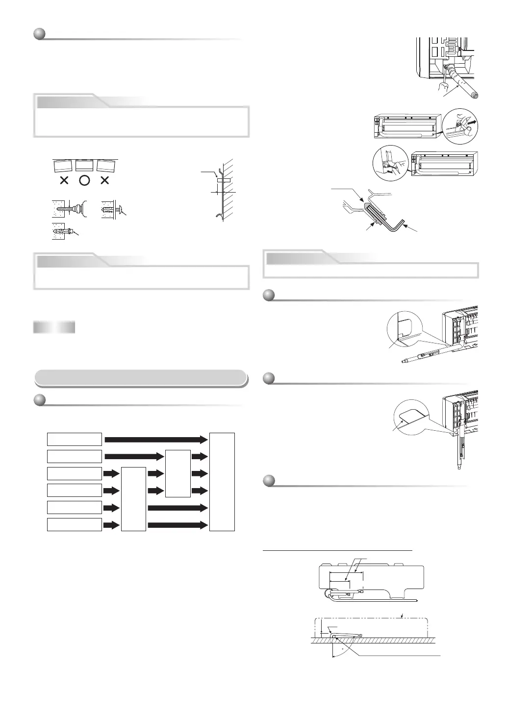
How to remove the drain hose
• The drain hose can be removed by removing the
screw securing the drain hose and then pulling out
the drain hose.
• When removing the drain hose, be careful of any
sharp edges of steel plate. The edges can injuries.
• To install the drain hose, insert the drain hose
fi rmly until the connection part contacts with heat
insulator, and then secure it with original screw.
How to remove the drain cap
Clip the drain cap by needle-nose
pliers and pull out.
How to fi x the drain cap
1) Insert hexagon wrench (4 mm)
in a center head.
2) Firmly insert the drain cap.
Firmly insert the drain hose and drain cap; otherwise, water may leak.
CAUTION
Drain hose
Do not apply lubricating oil
(refrigerant machine oil)
when inserting the drain
cap. Application causes
deterioration and drain
leakage of the plug.
Insert a hexagon wrench
(4 mm).
No gap
Piping and Drain Hose Installation
* Since dewing results in a machine trouble, make sure to insulate both
connecting pipes. (Use polyethylene foam as insulating material.)
Piping and drain hose forming
Rear right
Rear left
Bottom left
Left
Bottom right
Right
Die-cutting
front panel slit
Changing
drain hose
Piping preparation
1. Die-cutting front panel slit
Cut out the slit on the left or right side of the front panel for the left or right
connection and the slit on the bottom left or right side of the front panel
for the bottom left or right connection with a pair of nippers.
2. Changing drain hose
For leftward connection, bottom-leftward connection and rear-leftward
connection’s piping, it is necessary to change the drain hose and drain
cap.
Left-hand connection with piping
• Bend the connecting pipe so that it is laid within 43 mm above the wall
surface. If the connecting pipe is laid exceeding 43 mm above the wall
surface, the indoor unit may unstably be set on the wall.
When bending the connecting pipe, make sure to use a spring bender so
as not to crush the pipe.
Bend the connecting pipe within a radius of 30 mm.
To connect the pipe after installation of the unit (fi gure)
80
260 mm
210 mm
43 mm
Liquid side
Gas side
(To the forefront of fl are)
Outward form of indoor unit
R 30 mm (Use polisin (polyethylene)
core or the like for bending pipe.)
Use the handle of screwdriver, etc.
In case of bottom right or bottom left piping
• After scribing slits inside of the
front panel with a knife or a
making-off pin, cut them with a pair
of nippers or an equivalent tool.
Slit
In case of right or left piping
• After scribing slits inside of the
front panel with a knife or a
making-off pin, cut them with a pair
of nippers or an equivalent tool.
Slit
 Loading...