7
Evacuating
After the piping has been connected to the indoor unit, you can perform the
air purge together at once.
AIR PURGE
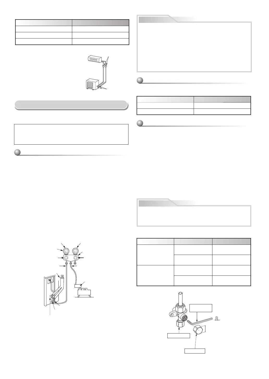
Evacuate the air in the connecting pipes and in the indoor unit using a
vacuum pump. Do not use the refrigerant in the outdoor unit. For details,
see the manual of the vacuum pump.
Be sure to use a vacuum pump with counter-fl ow prevention function so
that inside oil of the pump does not fl ow backward into pipes of the
air conditioner when the pump stops.
(If oil inside of the vacuum pump enters the air conditioner, which use
R32 or R410A, refrigeration cycle trouble may result.)
1. Connect the charge hose from the manifold valve to the service port of
the packed valve at gas side.
2. Connect the charge hose to the port of the vacuum pump.
3. Open fully the low pressure side handle of the gauge manifold valve.
4. Operate the vacuum pump to start evacuating. Perform evacuating for
about 15 minutes if the piping length is 20 meters. (15 minutes for
20 meters) (assuming a pump capacity of 27 liters per minute)
Then confi rm that the compound pressure gauge reading is –101 kPa
(–76 cmHg).
5. Close the low pressure side valve handle of the gauge manifold valve.
6. Open fully the valve stem of the packed valves (both gas and liquid
sides).
7. Remove the charging hose from the service port.
8. Securely tighten the caps on the packed valves.
Using a vacuum pump
Packed valve at liquid side
Service port (Valve core (Setting pin))
Packed valve at gas side
Vacuum
pump
Vacuum pump adapter for
counter-fl ow prevention
Charge hose
Handle High
(Keep full closed)
Manifold valve
Pressure gauge
Compound pressure gauge
Handle Low
Charge hose
Connecting pipe
–101 kPa
(–76 cmHg)
CAUTION
• KEEP IMPORTANT 7 POINTS FOR PIPING WORK.
(1) Take away dust and moisture (inside of the connecting pipes).
(2) Tighten the connections (between pipes and unit).
(3) Evacuate the air in the connecting pipes using a VACUUM PUMP.
(4) Check gas leak (connected points).
(5) Be sure to fully open the packed valves before operation.
(6) Reusable mechanical connectors and fl ared joints are not allowed
indoors. When mechanical connectors are reused indoors, sealing
parts shall be renewed. When fl ared joints are reused indoors, the
fl are part shall be refabricated.
(7) Don’t operate air conditioner in case no refrigerant in the system.
Packed valve handling precautions
• Open the valve stem all the way out, but do not try to open it beyond the
stopper.
Pipe size of Packed Valve Size of Hexagon wrench
12.70 mm and smallers A = 4 mm
15.88 mm A = 5 mm
• Securely tighten the valve cap with torque in the following table:
Cap Cap Size (H) Torque
Valve Rod Cap
H17 - H19
14~18 N·m
(1.4 to 1.8 kgf·m)
H22 - H30
33~42 N·m
(3.3 to 4.2 kgf·m)
Service Port Cap
H14
8~12 N·m
(0.8 to 1.2 kgf·m)
H17
14~18 N·m
(1.4 to 1.8 kgf·m)
H
Hexagon wrench
is required.
Service Port Cap
Valve Rod Cap
CAUTION
Should be check the compressor operating condition while pumping
down process. It must not any abnormal sound, more vibration.
It is abnormal condition appears and must turn off the Air Conditioner
immediately.
Pump down process
1. Turn off the Air Conditioner system.
2. Connect the charge hose from the manifold valve to the service port of
the packed valve at gas side.
3. Turn on the Air Conditioner system in cooling operation more than
10 minutes.
4. Check the operating pressure of the system should be normal value.
(Ref. with product specifi cation)
5. Release the valve rod cap of both service valves.
6. Use the Hexagon wrench to turning the valve rod of Liquid side fully close.
(*Make sure no entering air into the system)
7. Continue operate Air Conditioner system until the gauge of manifold
dropped into the range of 0.5 - 0 kgf/cm².
8. Use the Hexagon wrench to turning the valve rod of Gas side fully close.
And turn off the Air Conditioner system immediately thereafter.
9. Remove the gauge manifold from the service port of the packed valve.
10. Securely tighten the valve rod cap to the both service valves.
(Unit : N·m)
Outer dia. of copper pipe Tightening torque
Ø6.35 mm 14 to 18 (1.4 to 1.8 kgf·m)
Ø9.52 mm 30 to 42 (3.0 to 4.2 kgf·m)
Ø12.70 mm 50 to 62 (5.0 to 6.2 kgf·m)
Flare at
indoor unit side
Flare at
outdoor unit side
• Tightening torque of fl are pipe connections
The operating pressure of R32 or R410A
is higher than that of R22 (approx.
1.6 times). It is therefore necessary to
fi rmly tighten the fl are pipe connecting
sections (which connect the indoor and
outdoor units) up to the specifi ed
tightening torque. Incorrect connections
may cause not only a gas leakage, but
also damage to the refrigeration cycle.


 To Next Page
 Loading...