6
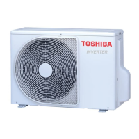
OUTDOOR UNIT
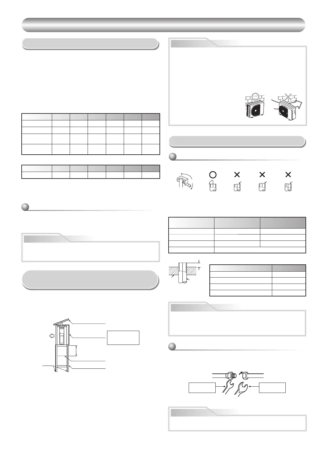
Installation Place
• A place which provides the spaces around the outdoor unit as shown in
the diagram.
• A place which can bear the weight of the outdoor unit and does not allow
an increase in noise level and vibration.
• A place where the operation noise and discharged air do not disturb your
neighbors.
• A place which is not exposed to a strong wind.
• A place free of a leakage of combustible gases.
• A place which does not block a passage.
• When the outdoor unit is to be installed in an elevated position, be sure to
secure its feet.
• The allowable length of the connecting pipe.
Model
RAS-05B2AVG-E RAS-07B2AVG-E RAS-10B2AVG-E RAS-13B2AVG-E RAS-16B2AVG-E RAS-18B2AVG-E
Chargeless Up to 10 m Up to 10 m Up to 10 m Up to 10 m Up to 10 m Up to 10 m
Maximum length 10 m 10 m 10 m 10 m 15 m 15 m
Additional
refrigerant charging
----
10 - 15 m
(20 g / 1 m)
10 - 15 m
(20 g / 1 m)
Maximum
refrigerant charging
0.44 kg 0.44 kg 0.49 kg 0.54 kg 0.78 kg 1.03 kg
• The allowable height of outdoor unit installation site.
Model
RAS-05B2AVG-E RAS-07B2AVG-E RAS-10B2AVG-E RAS-13B2AVG-E RAS-16B2AVG-E RAS-18B2AVG-E
Maximum height 8 m 8 m 8 m 8 m 8 m 8 m
• A place where the drain water does not raise any problems or with good
drainage.
• A place where it can be installed horizontally.
When the outdoor unit is installed in a place where the drain water might
cause any problems, Seal the water leakage point tightly using a silicone
adhesive or caulking compound.
CAUTION
Precautions for adding refrigerant
Use a scale having a precision with at least 10 g per index line when adding
the refrigerant.
Do not use a bathroom scale or similar instrument.
• Drain the water from all the drain holes directly.
• To protect the outdoor unit from snow accumulation, install a holding
frame, and attach a snow protection hood and plate.
* Do not use a double-stacked design.
Precautions about Installation in Regions
with Snowfall and Cold Temperatures
Snow protection plate
Snow protection hood
Snow accumulation line
Holding frame
At least
50 cm
Install at least 50 cm
above the snow
accumulation line.
Anchor
bolts
Front
90°
Obliquity Roughness Warp
CAUTION
1. Install the outdoor unit without anything blocking the air discharging.
2. When the outdoor unit is installed in a place always exposed to strong
wind like a coast or on a high storey of a building, secure the normal
fan operation using a duct or a windshield.
3. In particularly windy areas, install the unit such as to avoid admission
of wind.
4. Installation in the following places may result in trouble.
Do not install the unit in such places.
• A place full of machine oil.
• A saline-place such as the coast.
• A place full of sulfi de gas.
• A place where high-frequency
waves are likely to be generated
as from audio equipment, welders,
and medical equipment.
Strong
wind
Refrigerant Piping Connection
1. Cut the pipe with a pipe cutter.
2. Insert a fl are nut into the pipe and fl are the pipe.
• Projection margin in fl aring : A (Unit : mm)
RIDGID (clutch type)
Outer dia.
of copper pipe
Tool used
Conventional tool
used
Ø6.35 0 to 0.5 1.0 to 1.5
Ø9.52 0 to 0.5 1.0 to 1.5
Ø12.70 0 to 0.5 1.0 to 1.5
Pipes thickness 0.8 mm or more
Flaring
IMPERIAL (wing nut type)
Outer dia. of copper pipe Tool used
Ø6.35 1.5 to 2.0
Ø9.52 1.5 to 2.0
Ø12.70 2.0 to 2.5
Pipes thickness 0.8 mm or more
A
Die
Pipe
• Do not scratch the inner surface of the fl ared part when removing
burrs.
• Flare processing under the condition of scratches on the inner surface
of fl are processing part will cause refrigerant gas leak.
CAUTION
Flare nut
Half union
Externally
threaded side
Internally
threaded side
Use a wrench to secure. Use a torque wrench to tighten.
Align the centers of the connecting pipes and tighten the fl are nut as far as
possible with your fi ngers. Then tighten the nut with a spanner and torque
wrench as shown in the fi gure.
Tightening connection
CAUTION
Do not apply excess torque. Otherwise, the nut may crack depending on
the conditions.


 To Next Page
 Loading...