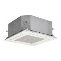
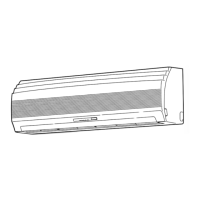
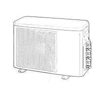
Pipe connection
1. Make wire and pipe connections for each indoor unit
separately.
2. Align the centres of the connecting pipes and tighten the
flare nut as much as possible with your fingers, then tighten
the nut using a torque wrench. Be sure to tighten the nut at
the specified torque value.
• If you use one outdoor unit for several indoor units of a
different class, connect the largest one first A, then
connect the rest in the order B to E.
• Do not remove the flare nuts for any ports you are not
going to use for connection.
• Do not leave the flare nut unattached for a long period of
time.
• Use a different-diameter joint if the diameters of the
connection port and connection piping are different.
• Mount the different-diameter joint on the connection port of
the outdoor unit.
CAUTION
• KEEP IMPORTANT 6 POINTS FOR PIPING
WORK.
(1)
(2)
Take away dust and moisture (inside of the
connecting pipes).
Tighten the connections (between pipes and
unit).
(3) Evacuate the air in the connecting pipes using a
VACUUM PUMP.
(4) Check gas leak (connected points).
(5) Be sure to fully open the packed valves before
operation.
(6) Reusable mechanical connectors and flared joints
are not allowed indoors. When mechanical
c
onnectors are reused indoors, sealing parts
shall
be renewed. When flared joints
are reused
indoors, the flare part
shall be refabricated.
6. Tighten all the caps on the valves securely, then perform a gas leak
inspection.
• The cap with the 9.52 mm outer diameter is available in two sizes in
accordance with the type of packed valve for which the cap is used.
The tightening torque depends on the width across flats of the cap s
check it in the table below.
Service valve
Tighten torque
Valve stem cap Service port cap
mm N•m kgf•m N•m kgf•m
Liquid side
(9.52)
H19 mm 14 to 18 1.4 to 1.8
‒ ‒
H22 mm 33 to 42 3.3 to 4.2
Gas side (12.7) 33 to 42 3.3 to 4.2 14 to 18 1.4 to 1.8
Air Purge
From the sake of environmental protection, use a vacuum pump to extract
the air during installation.
* Prepare a 4 mm hexagon wrench.
1. Connect a charge hose.
• Make sure that the Handle Hi of the gauge manifold valve is closed fully.
• Connect the port of the gauge manifold valve and the service port (Valve
core (Setting Pin)) using the charge hose.
NOTE
If a control valve or charge valve is attached to the charge hose, leak
of R32 refrigerant can be avoided.
2. Open the Handle Low of the gauge manifold valve fully, then operate the
vacuum pump.
•
•
Loosen the flare nut of the at the gas end a little to make sure that air i
taken in, then tighten the nut.
If you find air is not taken in, make sure that the charge hose i
connected to the port(s) securely.
• Perform extraction for about 40 minutes and make sure that the
compound pressure gauge reading is –101 kPa (–76 cmHg).
• If the compound pressure gauge reading is not –101 kPa (–76 cmHg),
there is a possibility air is being taken in from the port(s).
• Make sure that the charge hose is connected to the port(s) securely.
3. Close the Handle Low of the gauge manifold valve fully, then stop
operating the vacuum pump.
•
•
Leave the gauge and pump as they are for 1 or 2 minutes, then make
sure that the compound pressure gauge reading stays at –101 kPa
(–76 cmHg).
You need not add refrigerant if the piping length is 40 m or less.
If the length exceeds 41 m, add 20 g of refrigerant per 1 meter over.
4. Disconnect the charge hose from the service port, then open the valve
stem fully using a 4 mm hexagon wrench.
Hexagon wrench is
required.
Valve stem cap
Service port cap
4 mm
5. Tighten the service valve stem cap and service port cap securely.
CAUTION
Use a torque wrench and tighten the nut at
the specified torque value

 Loading...

